Electronic Project: Build a LED dimmer with a potentiometer
In this post I will show you how to build a LED dimmer with a potentiometer.
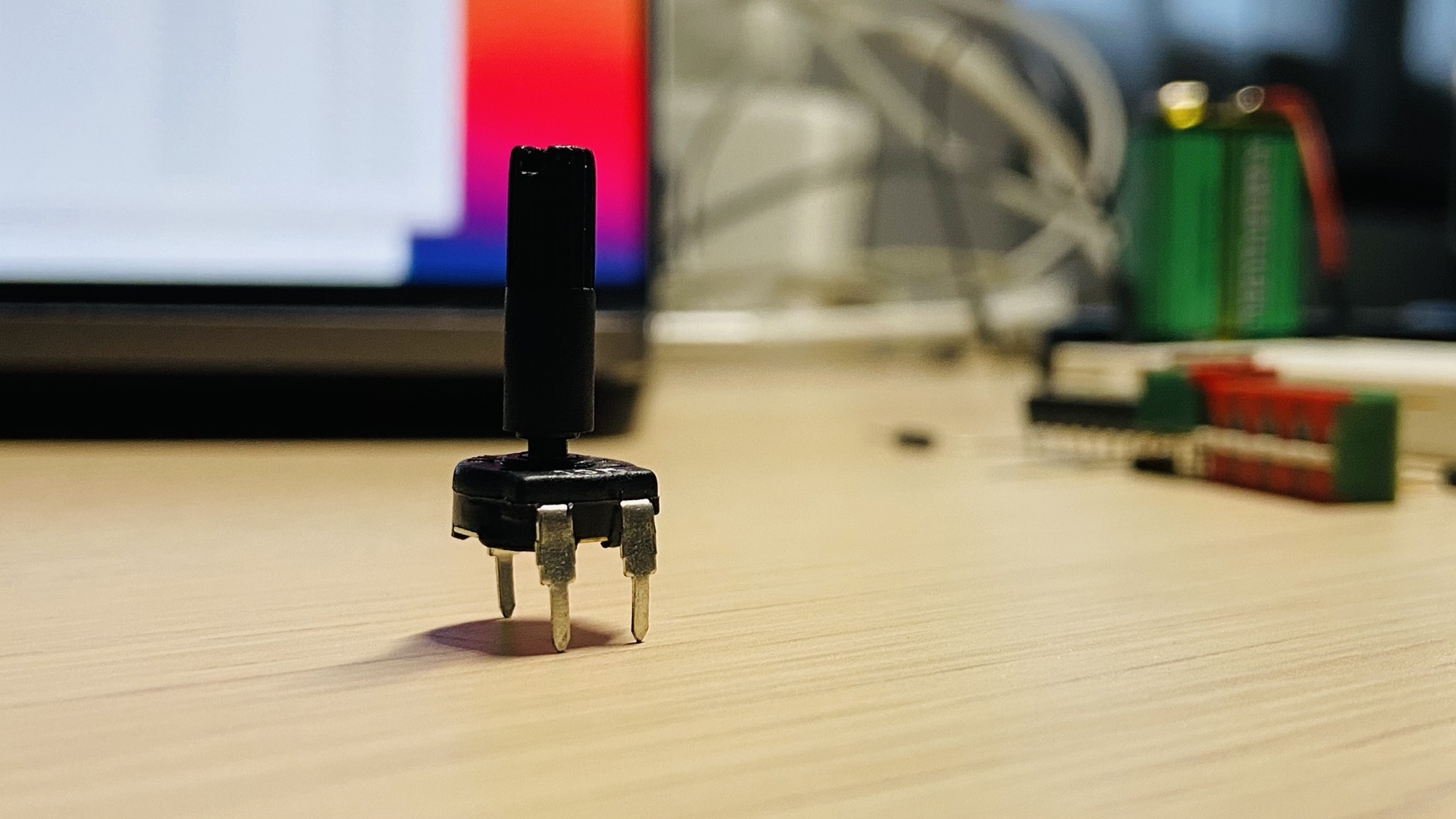
You need 4 things: a potentiometer, like this 10kΩ one:
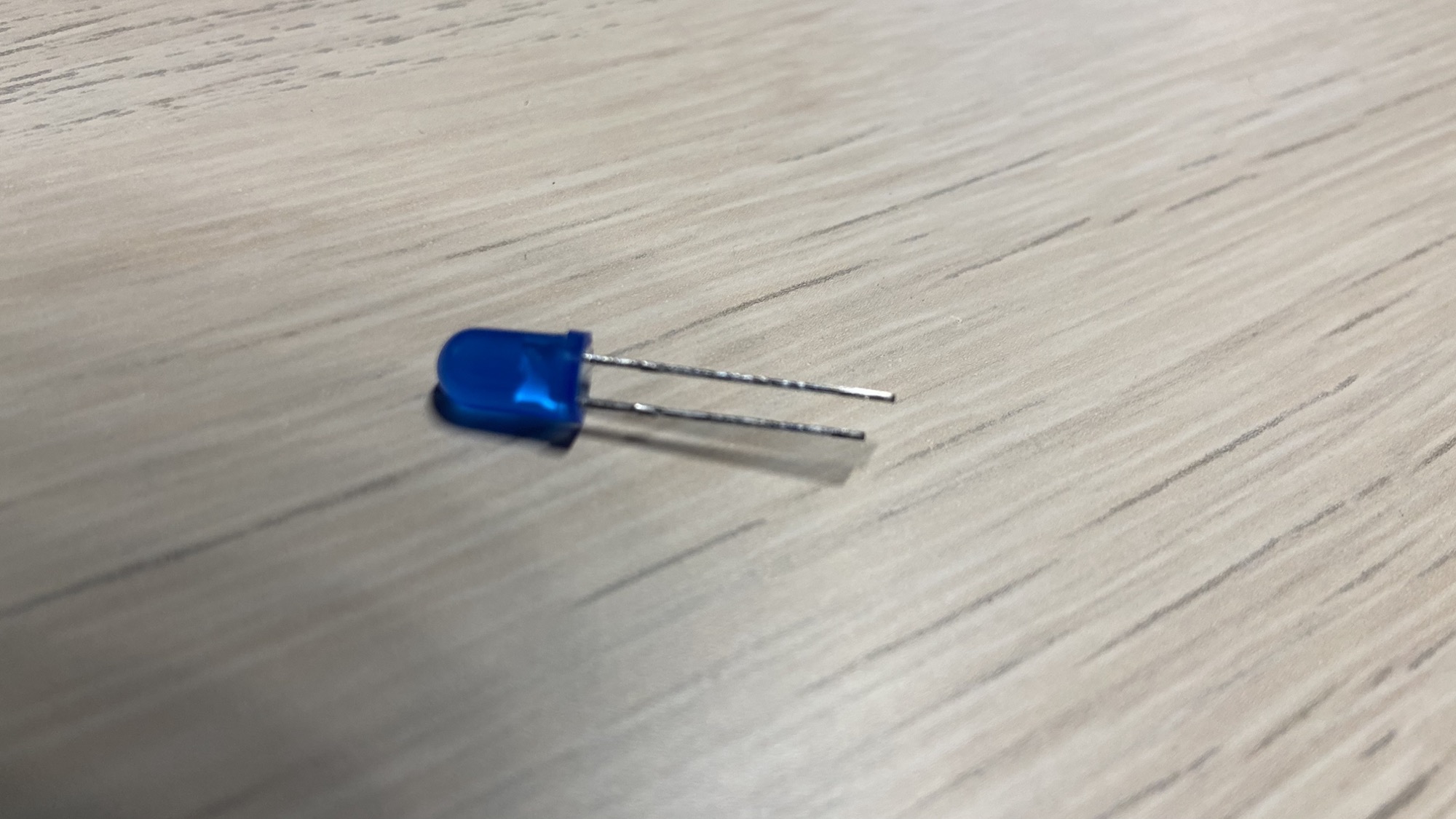
A 5mm LED, any color you like:
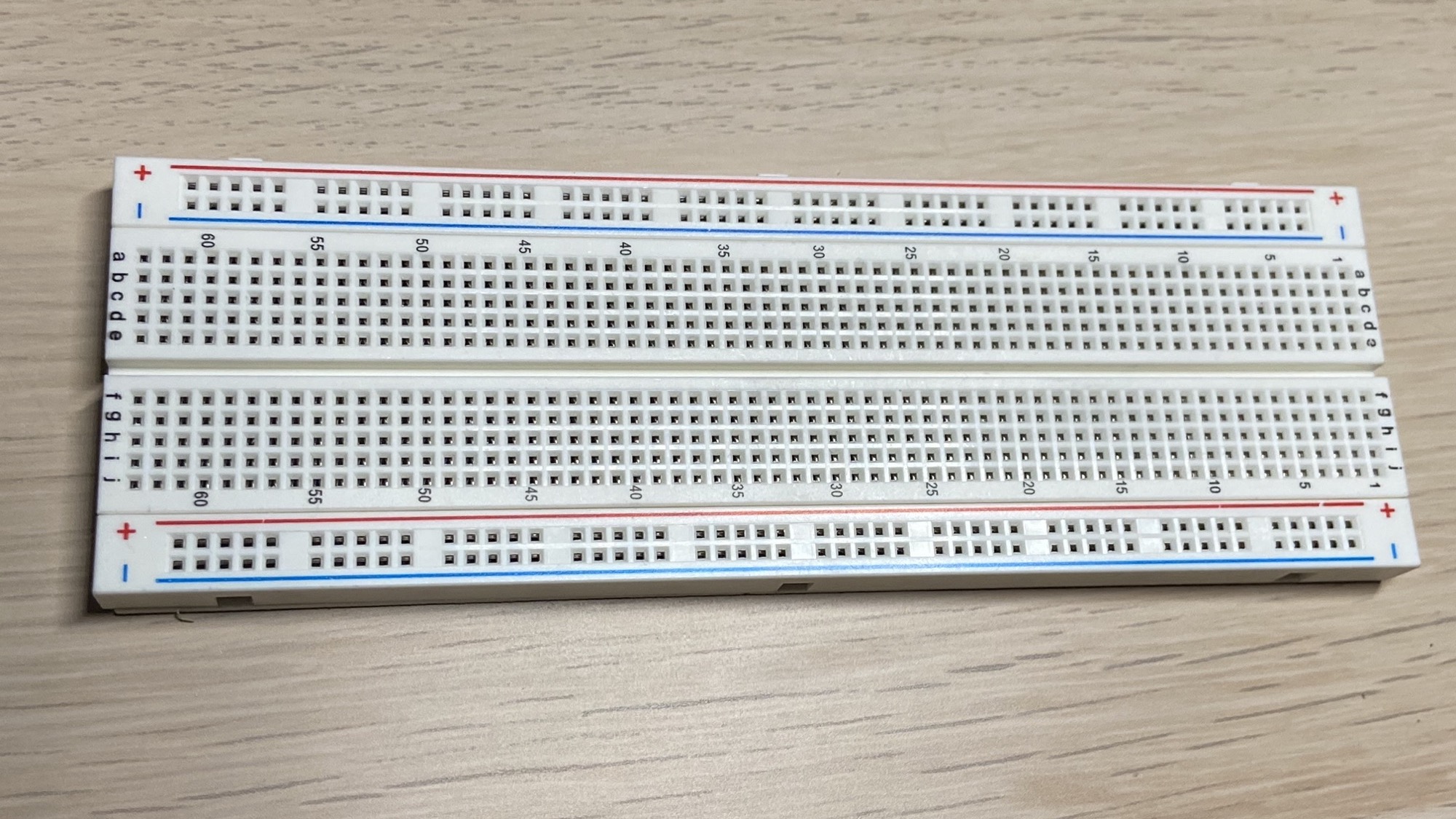
A breadboard, where we put our components on:
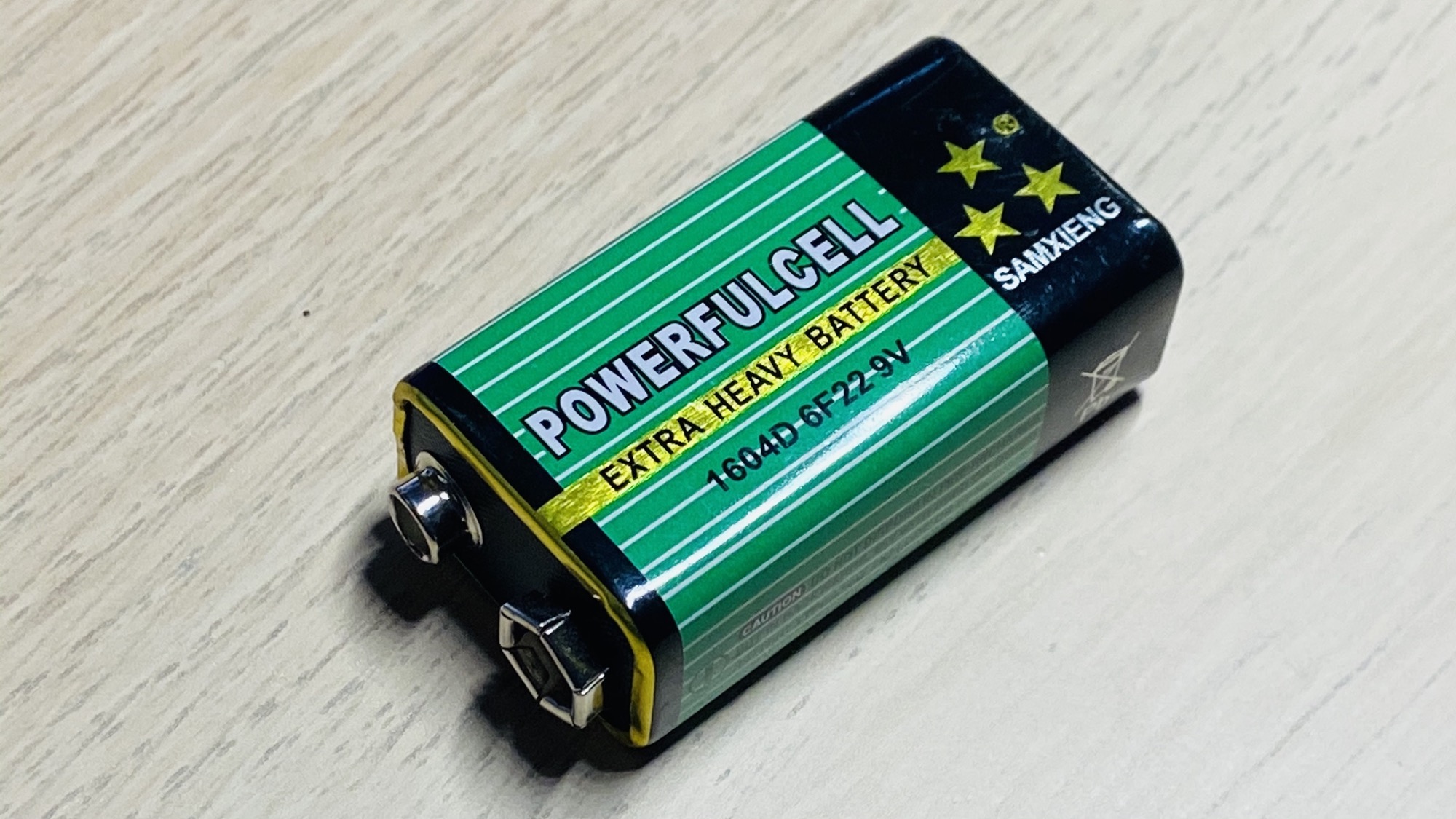
And a battery. I use a 9V battery:
Plus some wires.
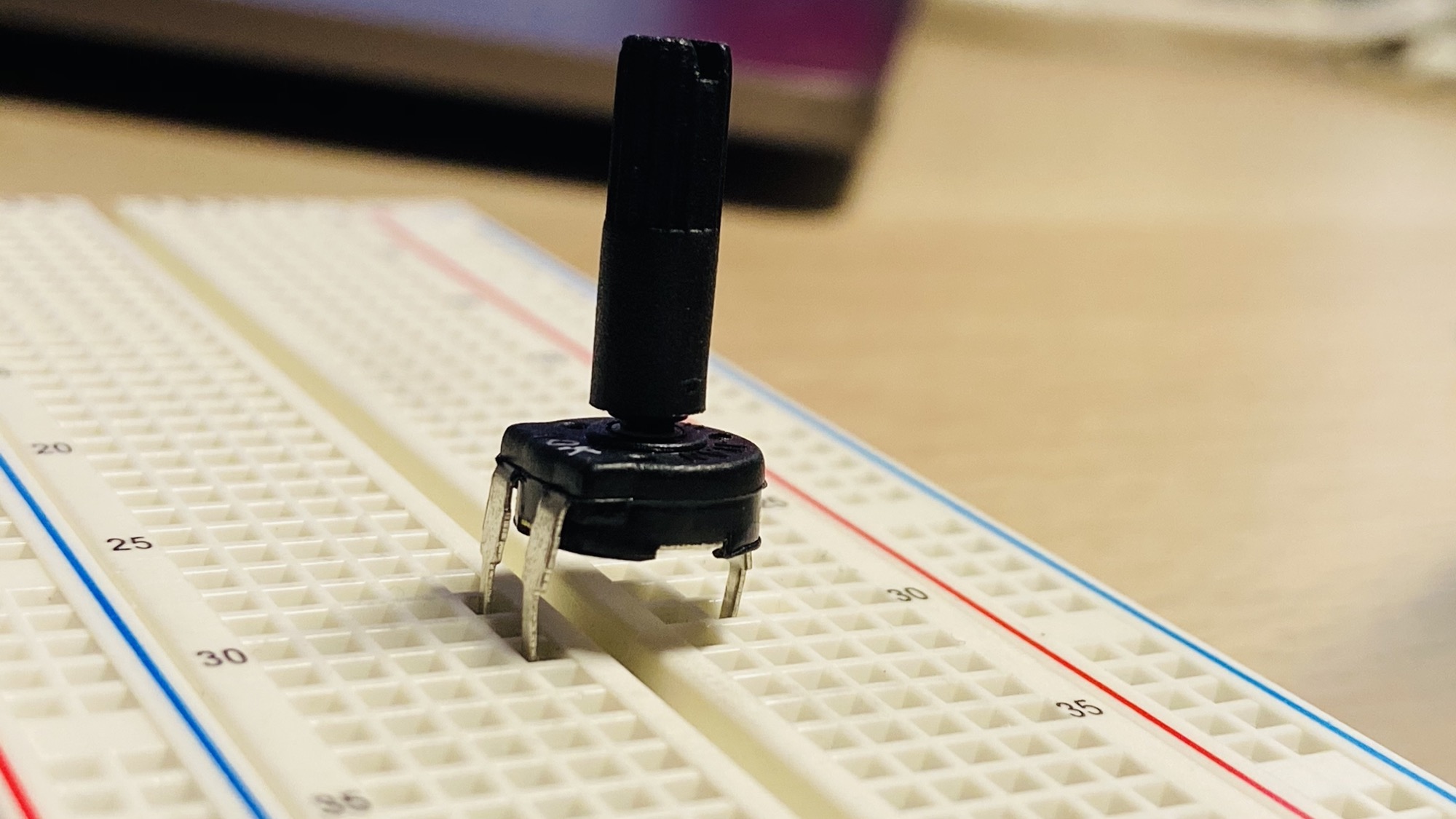
Start by putting the potentiometer on the board, in any place you want, with the 2 input pins on one side of the board, and 1 output pin on the other side:
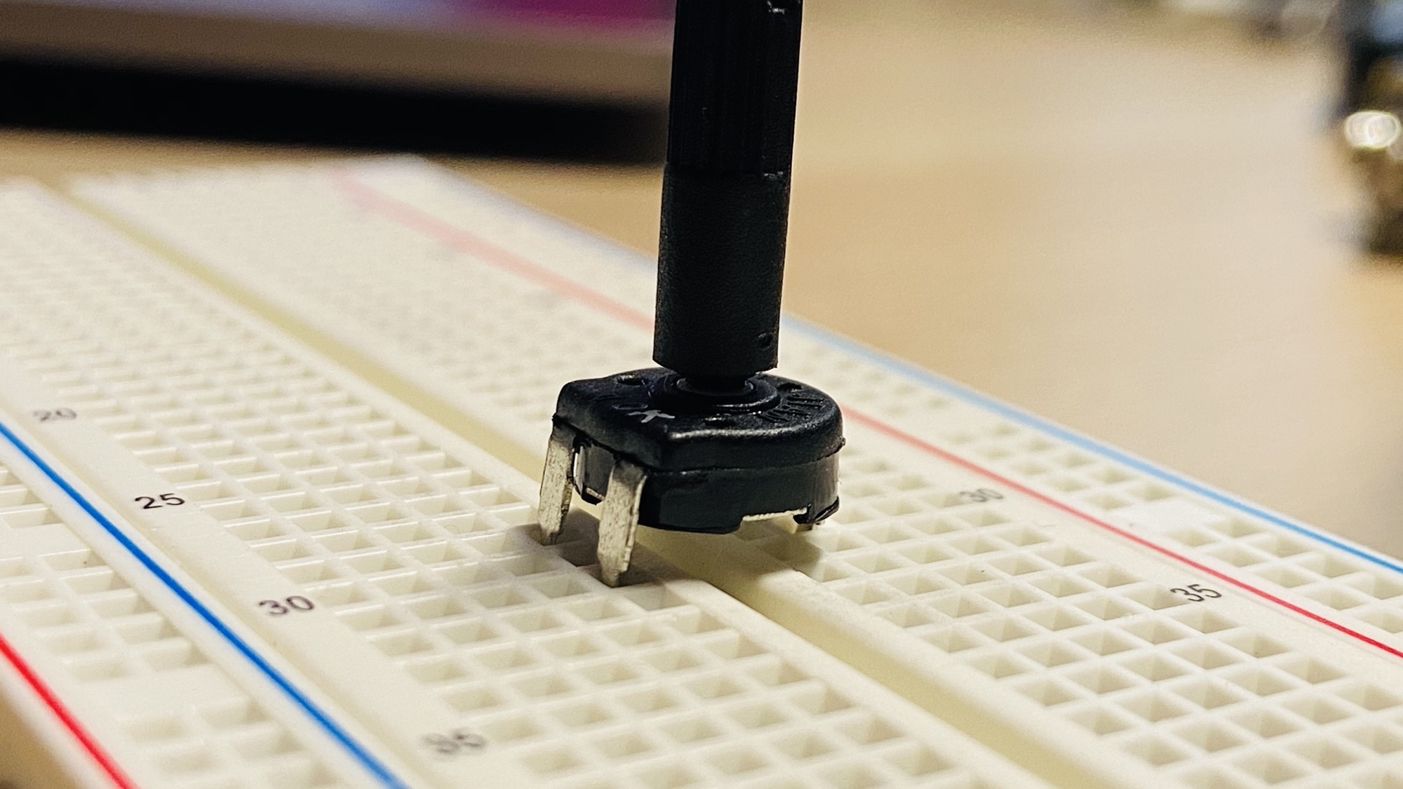
Press it down to connect it to the breadboard:
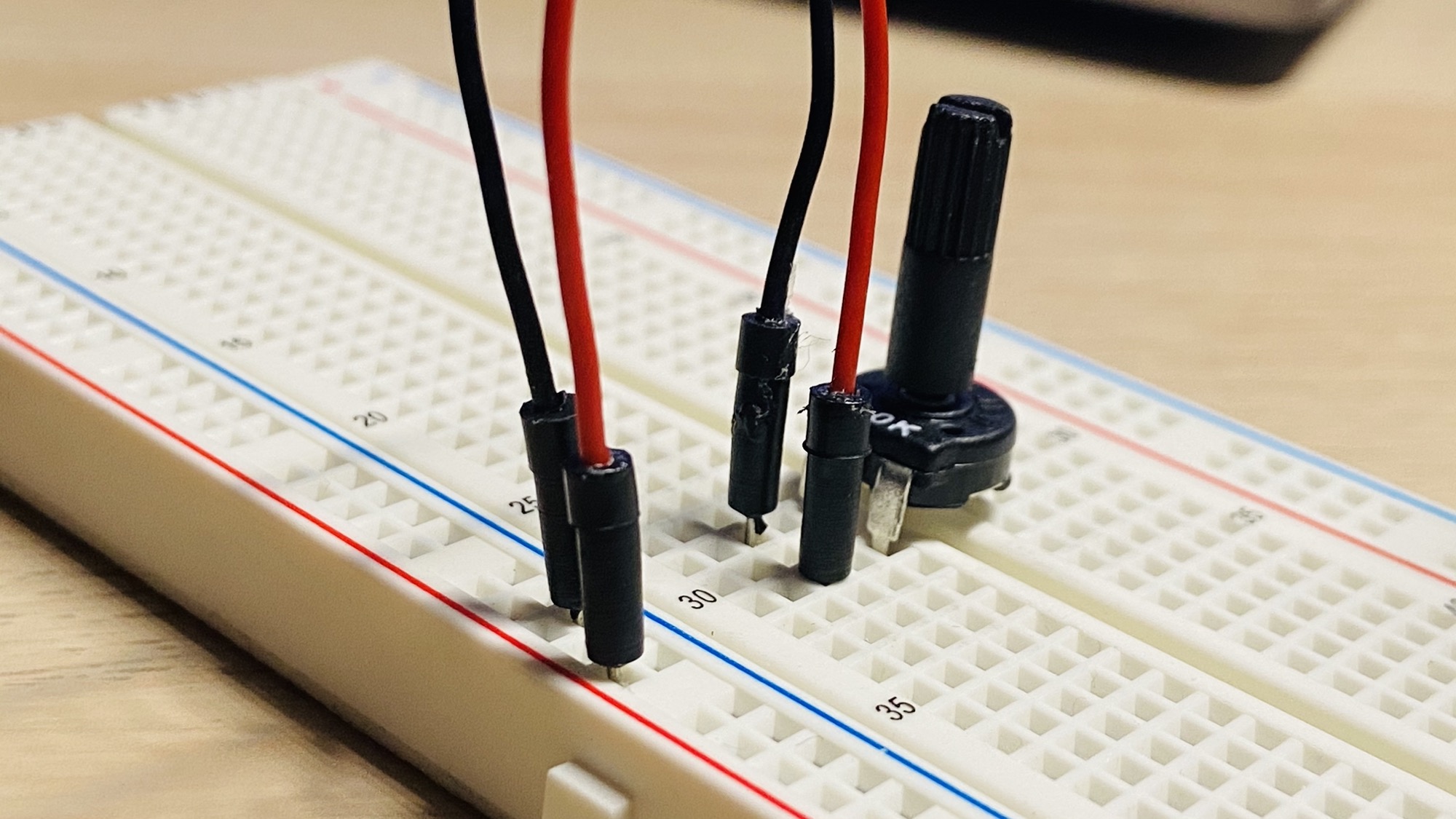
Now connect the - pin to the blue line of the breadboard which we’ll connect to the negative pole of the battery, and the + pin to red line which we’ll later connect to the + pole of the 9V battery.
I use for convention a black wire for the - (GND) and a red wire for the positive +.
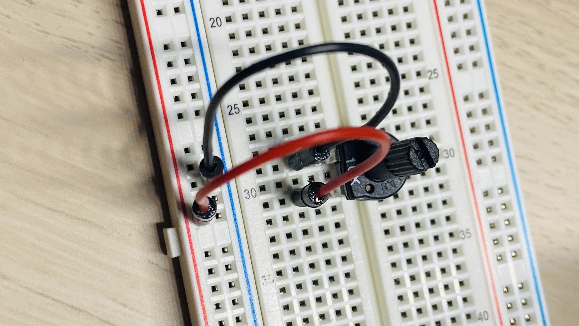
Make sure the potentiometer is completely turned to the left, counterclockwise.
Now connect a LED to the output pin, put the longest wire of the LED, the anode, on the same row. Then connect the cathode, the shortest wire, to the - blue line of the breadboard:
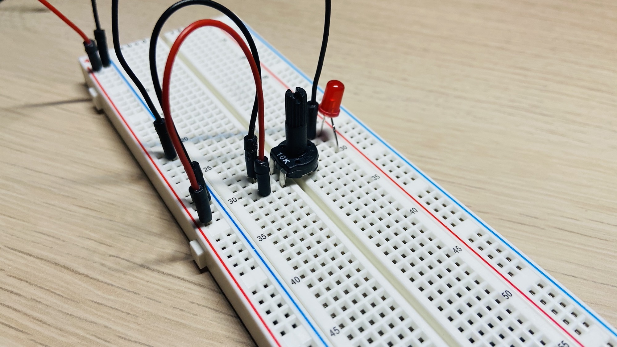
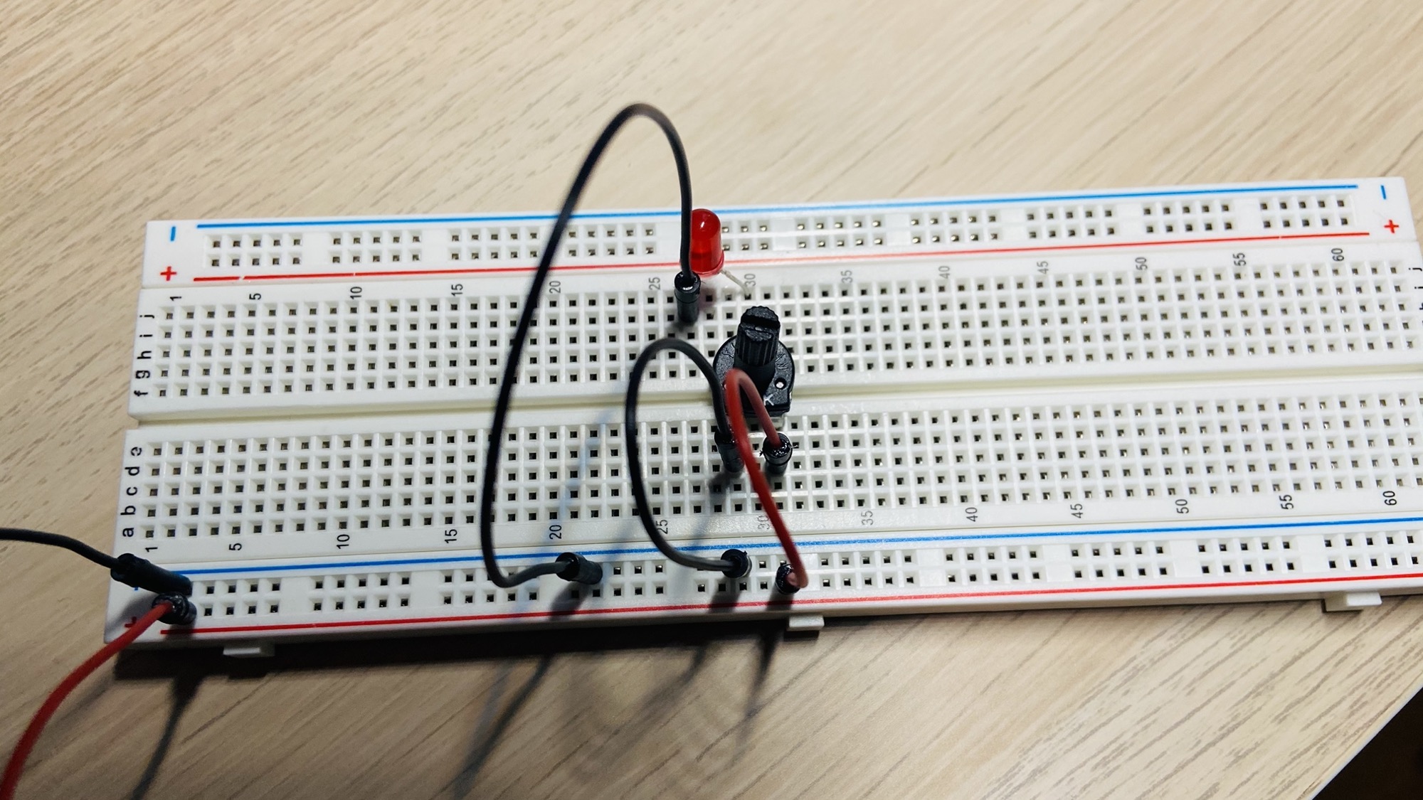
Great, now connect a 9V battery and you’ll see the LED still turned OFF (assuming you turned the potentiometer all the way to the left, counterclockwise, which acts as a 10kΩ resistance in the example).
Be careful not to turn the potentiometer all the way to the right, or the LED could be damaged as the current will be too much to handle.
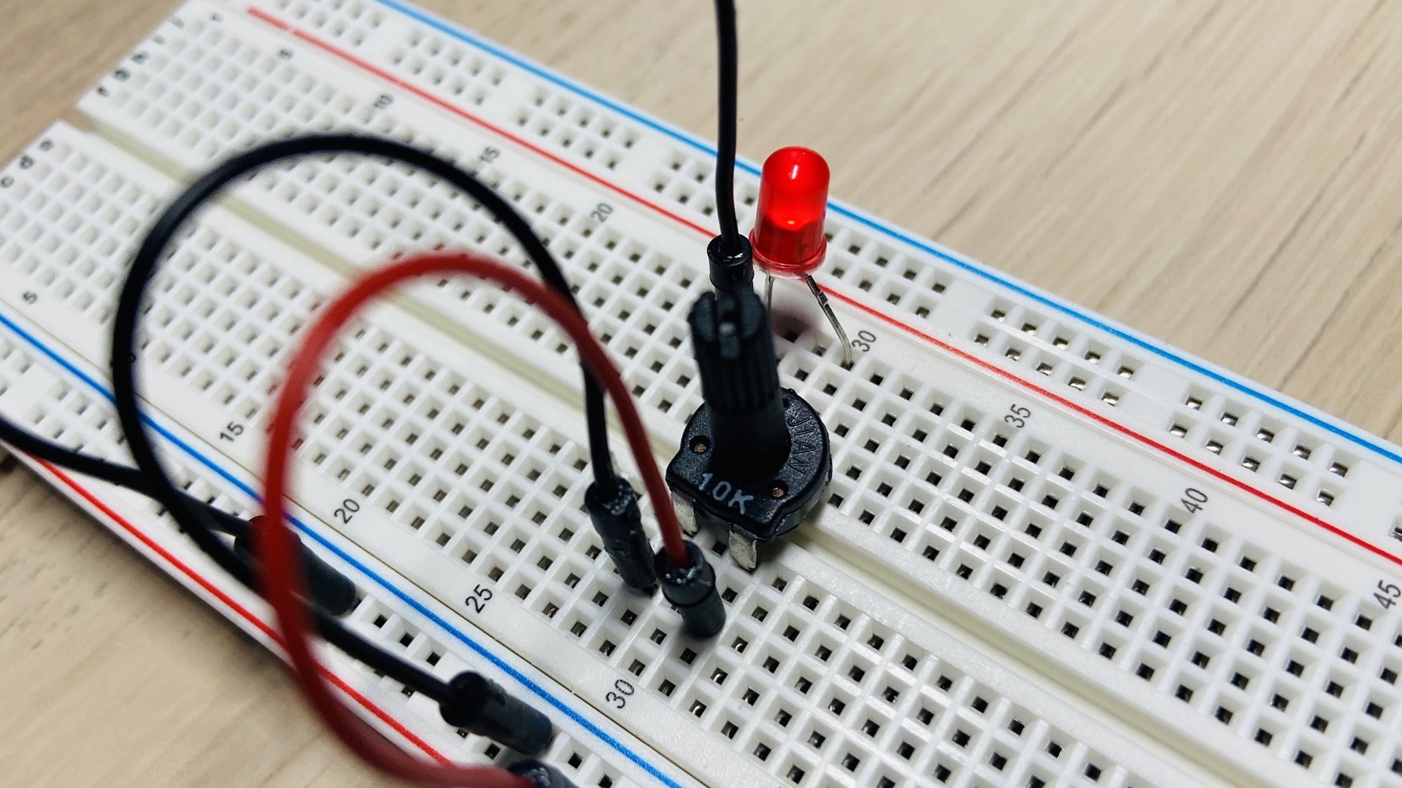
Rotate it slightly to the right and you’ll start see the light turning on, more and more intense as you turn the resistance down.
download all my books for free
- javascript handbook
- typescript handbook
- css handbook
- node.js handbook
- astro handbook
- html handbook
- next.js pages router handbook
- alpine.js handbook
- htmx handbook
- react handbook
- sql handbook
- git cheat sheet
- laravel handbook
- express handbook
- swift handbook
- go handbook
- php handbook
- python handbook
- cli handbook
- c handbook
subscribe to my newsletter to get them
Terms: by subscribing to the newsletter you agree the following terms and conditions and privacy policy. The aim of the newsletter is to keep you up to date about new tutorials, new book releases or courses organized by Flavio. If you wish to unsubscribe from the newsletter, you can click the unsubscribe link that's present at the bottom of each email, anytime. I will not communicate/spread/publish or otherwise give away your address. Your email address is the only personal information collected, and it's only collected for the primary purpose of keeping you informed through the newsletter. It's stored in a secure server based in the EU. You can contact Flavio by emailing flavio@flaviocopes.com. These terms and conditions are governed by the laws in force in Italy and you unconditionally submit to the jurisdiction of the courts of Italy.