Electronic components: Buttons
By Flavio Copes
An introduction to push buttons in electronics: how they close a circuit only while pressed, how to place one across a breadboard, and light a LED with it.
One useful component in our circuits is a button, also called a push button or tactile button.
It connects two parts of a circuit when the button is pressed. As soon as the button is released, the circuit is open and the current can’t circulate.
This makes it different from a switch. A switch keeps its state after you let it go. A button is momentary: it only conducts while your finger holds it down. That’s what you want for things like “turn on the LED while I press”, or later, for sending input to an Arduino.
Here’s a typical button:
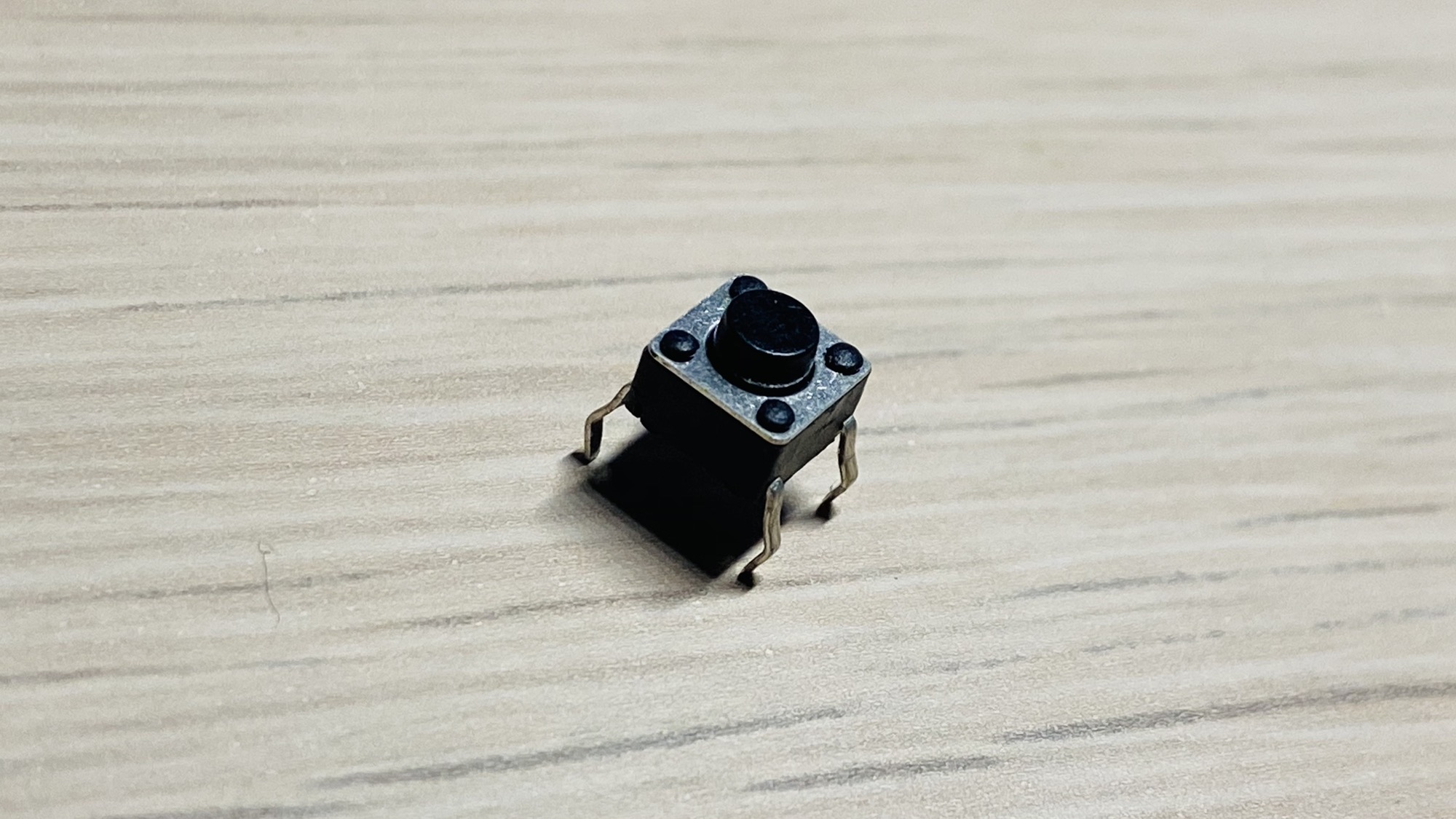
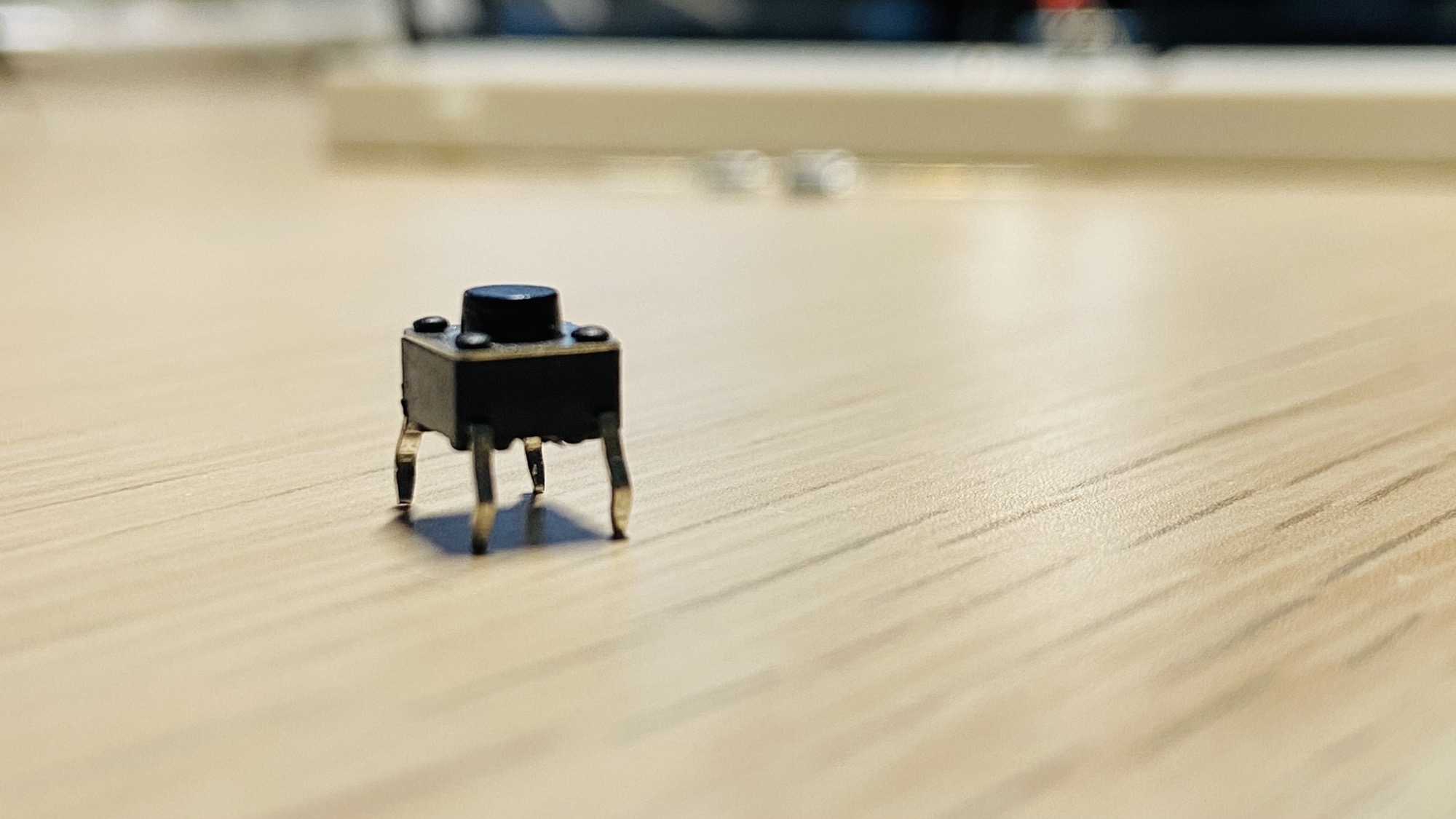
How are the pins connected?
The button has 4 pins, but electrically there are only 2 sets of connections that can be closed at the same time. The connections are on the pins that are curved in the same way:
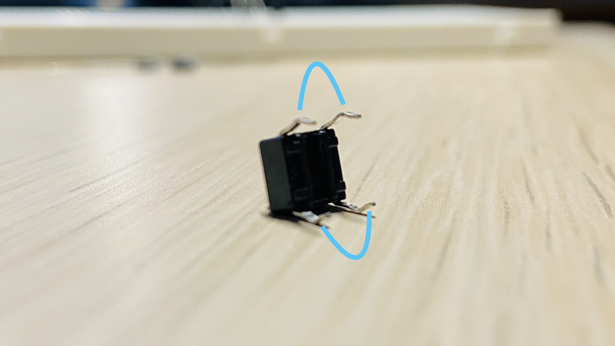
Pins in the same pair conduct all the time, pressed or not. They’re internally joined. Pressing the button is what connects one pair to the other.
If you’re not sure which pins belong together, set a multimeter to continuity mode and touch two pins. If it beeps without pressing the button, those two pins are on the same pair.
Placing the button on a breadboard
There’s one way to use this component in a breadboard, and it’s to put it in the middle:
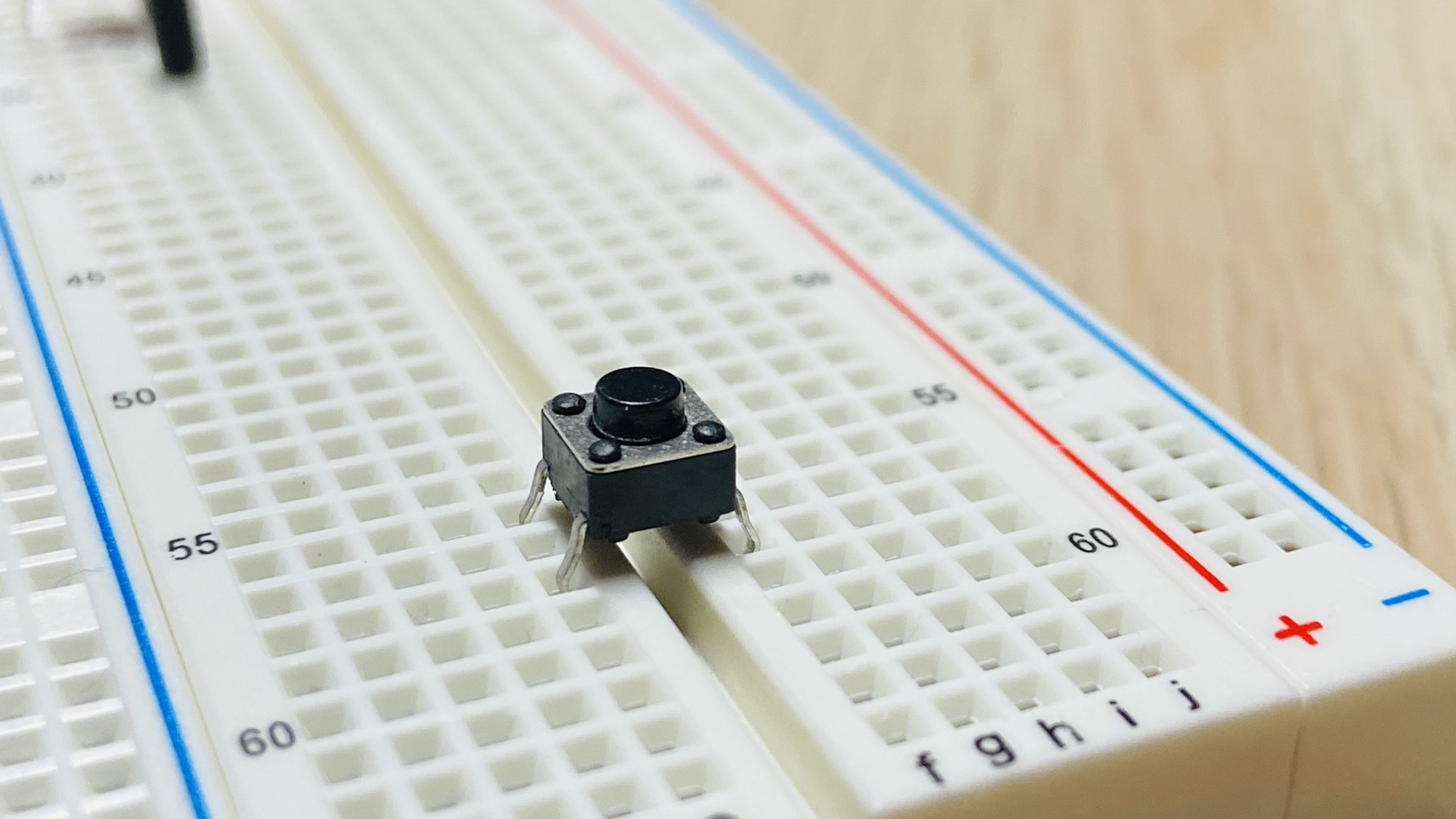
and there’s just one way to add it, you can’t go wrong. The pin spacing only fits across the center gap:
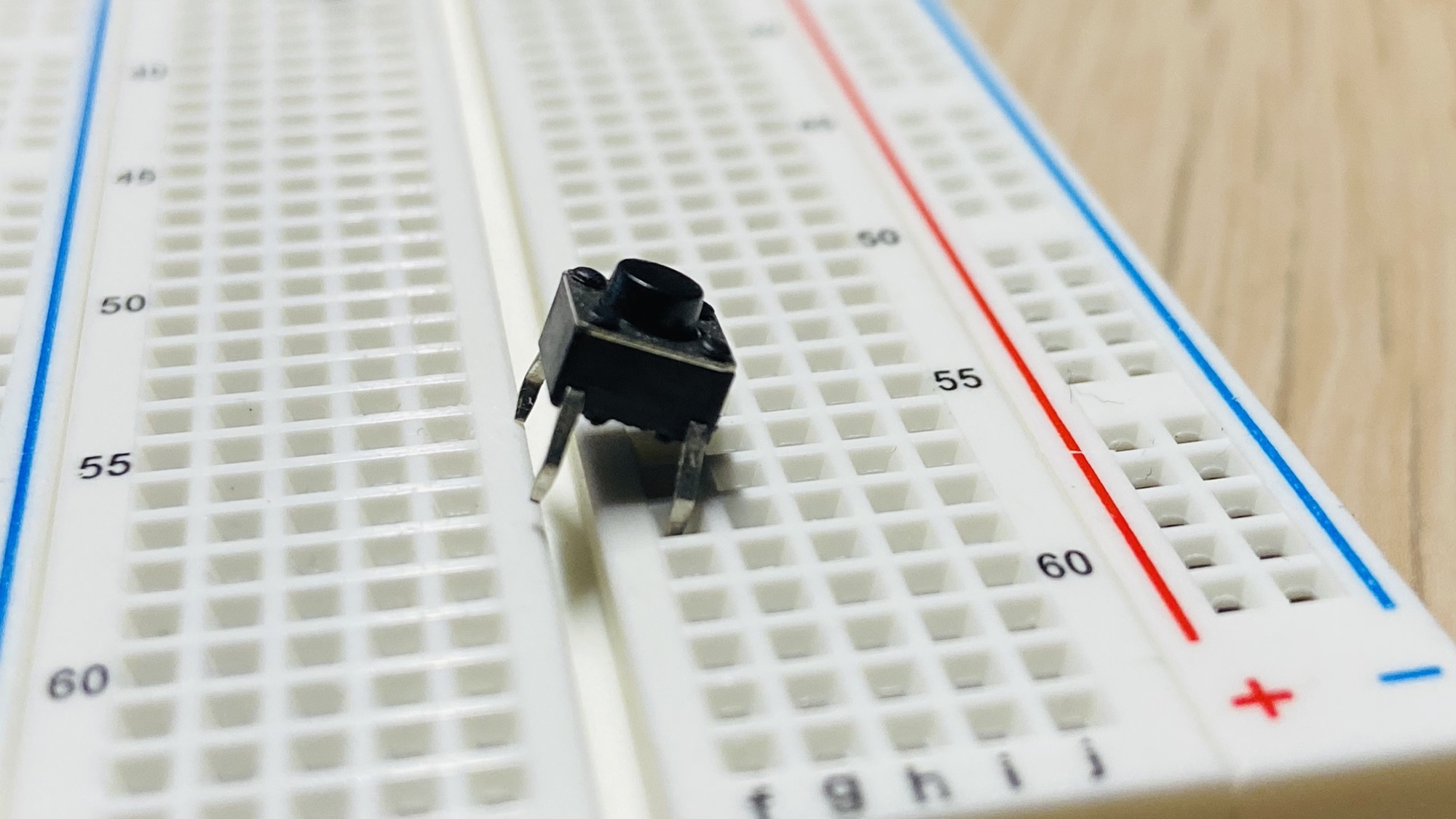
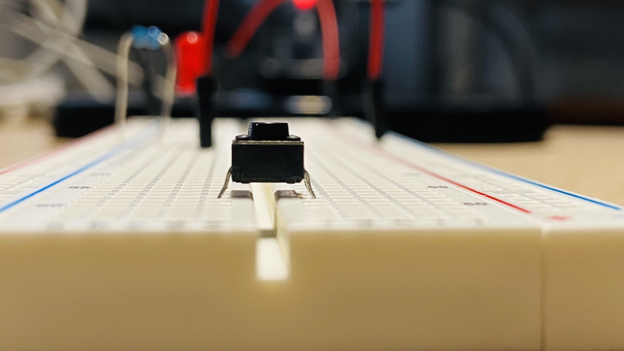
Then you can create a connection between 2 rows in the same part of the breadboard, like this:
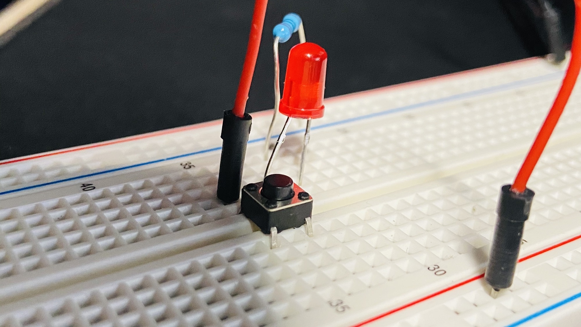
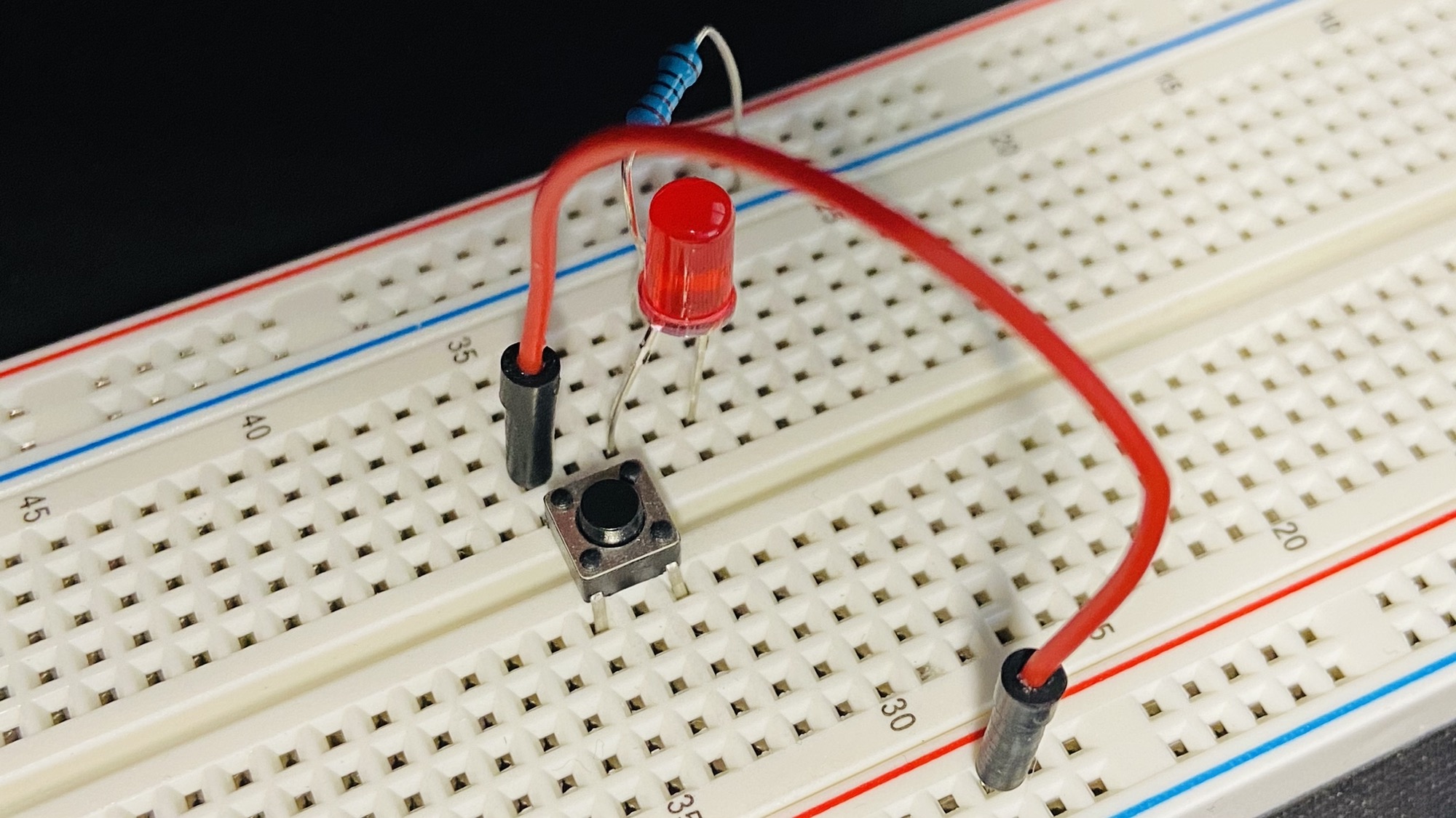
In the above circuit, the LED will turn on only when the button is pressed:
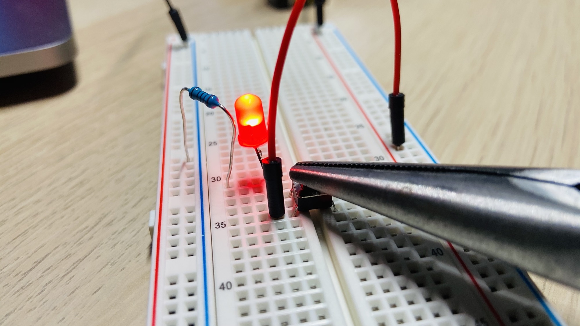
A common mistake
If you skip the breadboard and solder or clip wires directly to the pins, it’s easy to pick two pins that are already connected. The circuit is then always closed, and the LED stays on no matter what you do with the button.
The fix is the continuity test above: pick two pins that only conduct while the button is pressed.
On the breadboard, straddling the center gap avoids the problem entirely, because the gap forces the two sides of the circuit onto different pairs. That’s why we place the button there.
Want me to talk about your product? You can sponsor this site.
Related posts about electronics: