Arduino project: read analog input
By Flavio Copes
Learn how to read analog input on an Arduino with the analogRead() function, wiring a potentiometer to pin A1 to read values from 0 to 1023.
In this project we’re going to use a potentiometer and connect it to an analog input pin in the Arduino, and we’ll write a program that reads the current values.
In the Arduino Project #2 we saw how to read a digital input. The value read can be 0 or 1, LOW or HIGH.
This can be done using the digital I/O pins, numbered from 0 to 13.
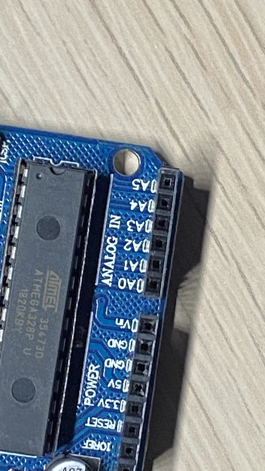
Analog I/O pins start with an A. On the Arduino Uno you can find 6 analog I/O pins A0 / A5:
On the Arduino MKR 1010 WiFi you have 7 analog I/O pins, from A0 to A6
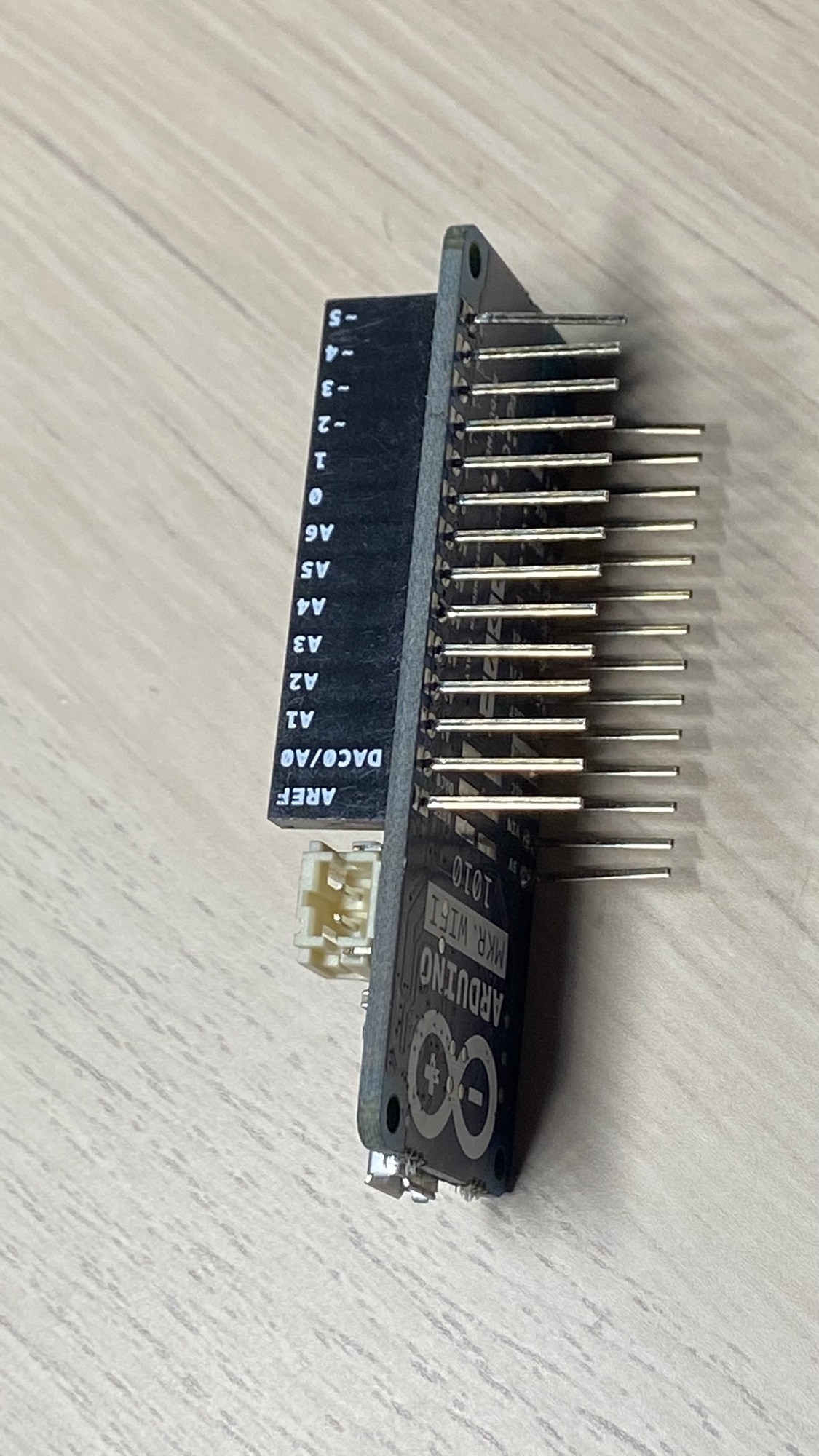
Different boards will have a different amount and placement of those pins. Those pins can be configured to be analog input or analog output.
A digital signal can only be high or low. An analog signal can hold a range of values, in the case of Arduino it goes from 0 to 1023, which maps to a level of tension on the input pun that goes from 0V to 5V.
All sorts of sensors will provide us analog values. Think about temperature sensors, distance sensors, sound sensors, motion sensors.. we can read the values from them using Arduino, and decide what to do with the data.
We do so using a function called analogRead().
But let’s start by building a little circuit.
In the project “Build a LED dimmer with a potentiometer” we build a simple circuit that controlled a LED light using a potentiometer. Let’s replicate a part of that circuit, except now instead of the LED we’ll put the Arduino.
If the potentiometer is turned all the way to the left, the value we read should be 0. All the way to the right the value we read should be 1023, and around the middle it should be 512.
Here is the circuit, made with a 10kΩ potentiometer:
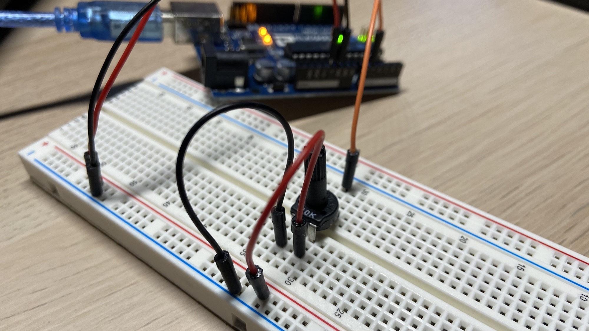
We get 0V and 5V from the power output pins of the Arduino and we connect them to the breadboard. Then we connect those levels of tension to the potentiometer input pins, and we get the output pin which we connect to the analog pin A1:
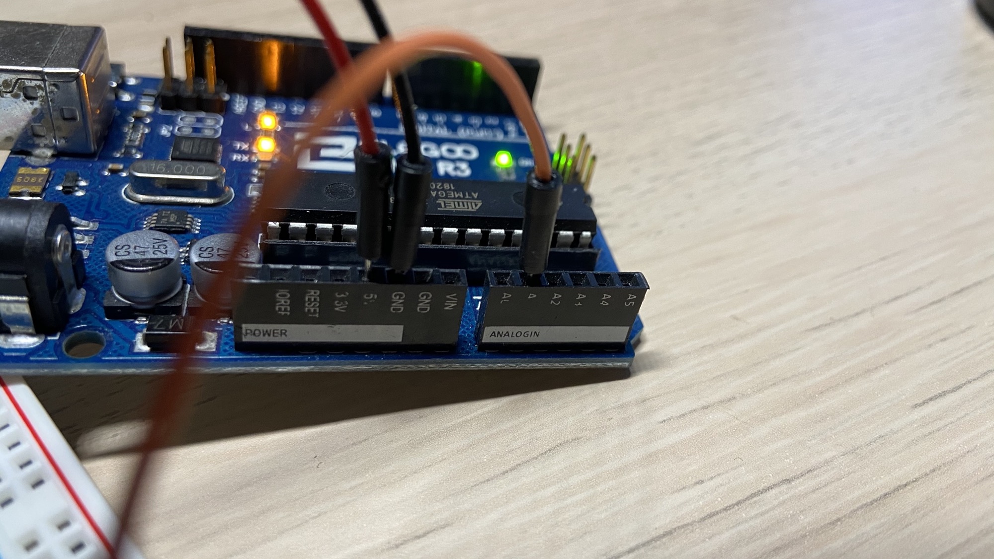
We write a program to read from that pin, and we print the value read to the serial interface, so we can read it from the Arduino IDE serial monitor:
void setup() {
    Serial.begin(9600);
}

void loop() {
    int value = analogRead(A1);
    Serial.println(value);
}
Note that I didn’t explicitly set the A1 pin to be an input pin, because a pin is input by default. If I wanted to write to that instead I’d have to configure it with pinMode() in setup().
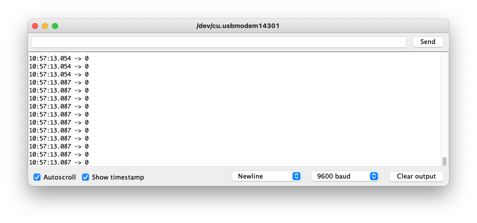
Here is our program running. With the potentiometer all turned to the left we read 0:
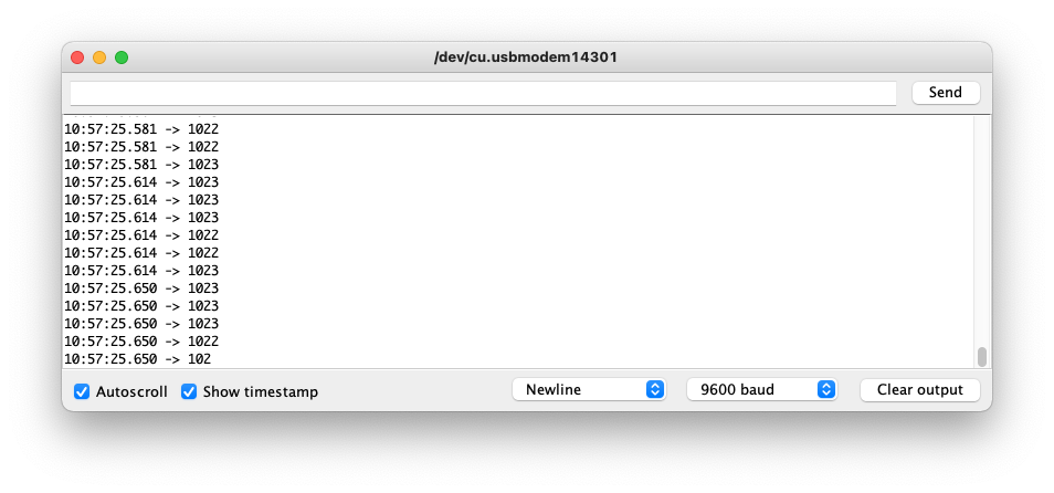
With the potentiometer all turned to the left we read 1023 (and sometimes 1022 as we’re working with analog values and it’s not 100% precise):
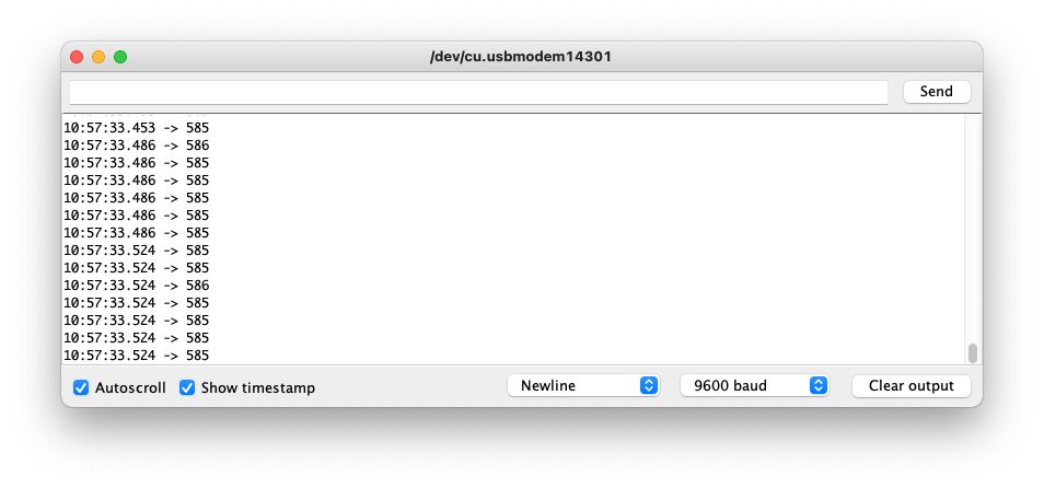
and in the middle you will read values that indicate how much the potentiometer is turned:
Want me to talk about your product? You can sponsor this site.
Related posts about electronics: