Electronic components: LEDs
By Flavio Copes
Learn how to use a 5mm LED in your circuits: connect anode to plus and cathode to minus, add a resistor to limit current, and understand its voltage drop.
A Light Emitting Diode, also called LED, is one of the first electronic components you use in your experiments, because it’s simple to use and due to its nature it’s perfect to explore all the concepts we’re learning.
There are various kinds of LEDs, for various applications and uses. Some are really tiny, for use in grids. Some are high-power, like the ones used for automotive lights.
The ones we’ll talk about here is the ones commonly used for prototyping, the 5mm LEDs.
This LED has 2 leads, one is the anode and other is the cathode.
Typically the anode is longer than the cathode:
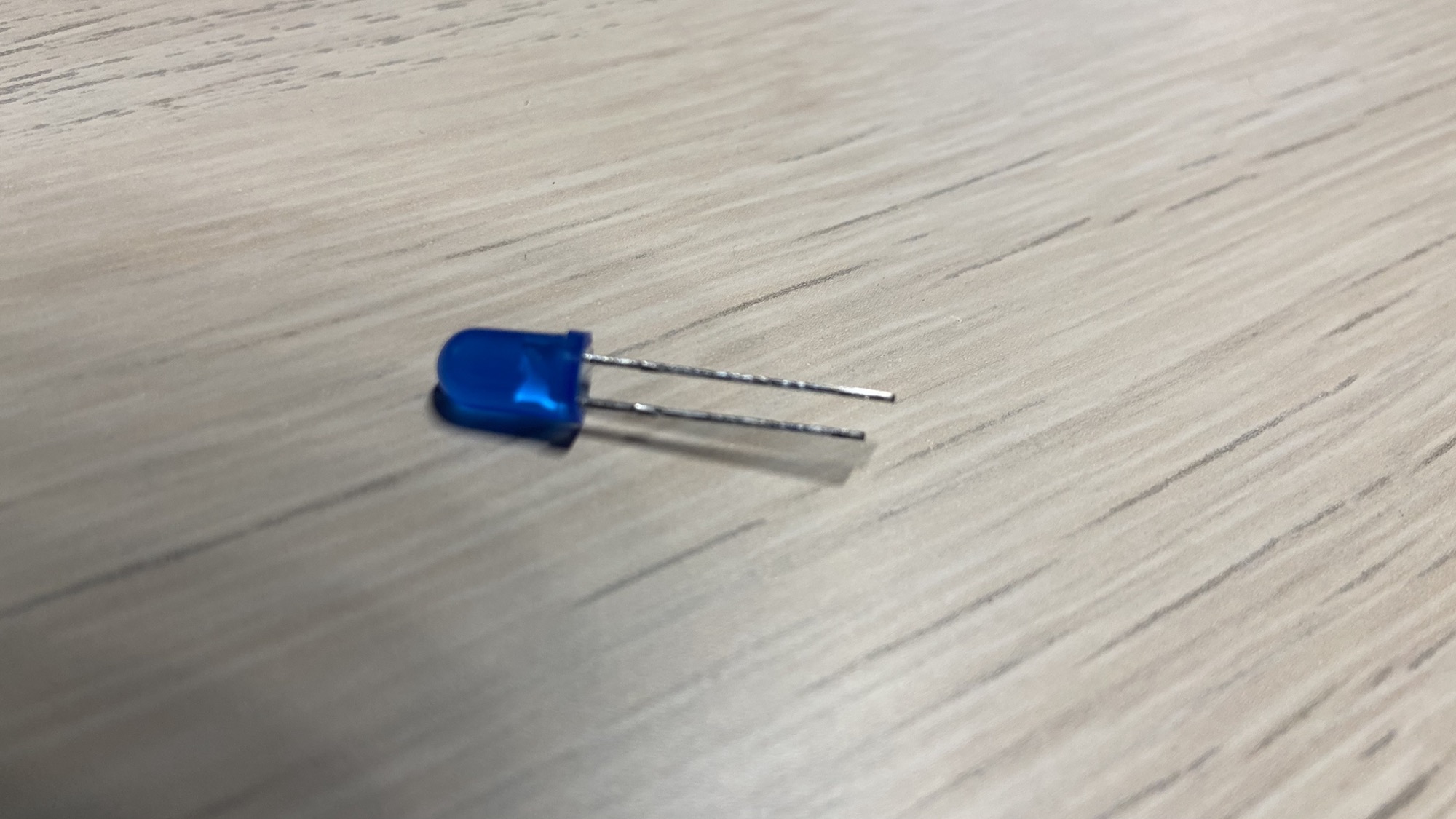
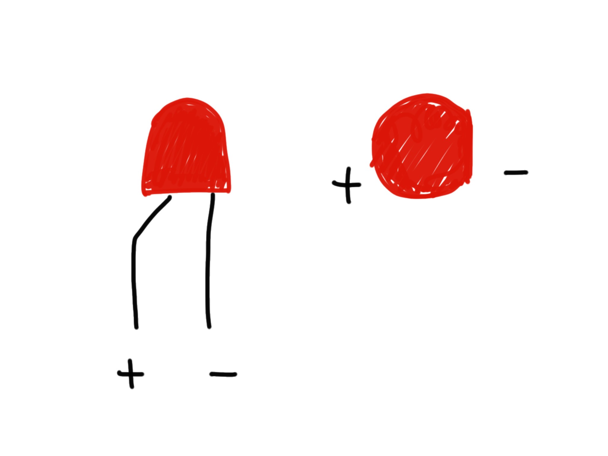
We connect the anode to the + positive lead and the cathode to the -. It’s important to not invert this order, or the LED will not work.
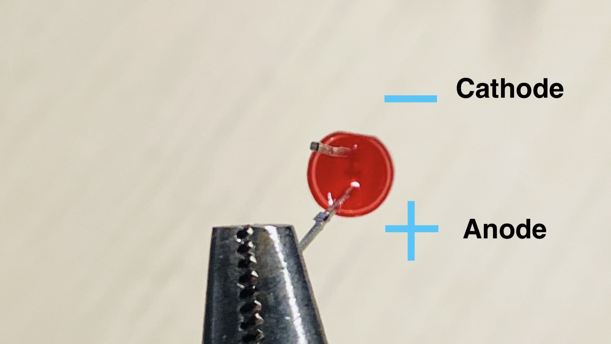
Note that the cathode has a shorter lead, but if the leads are cut it might be hard to figure out which connection is the cathode - in the case of a 5mm LED, the cathode has a little cut through the shape, it’s not a perfect circle like in the side of the anode.
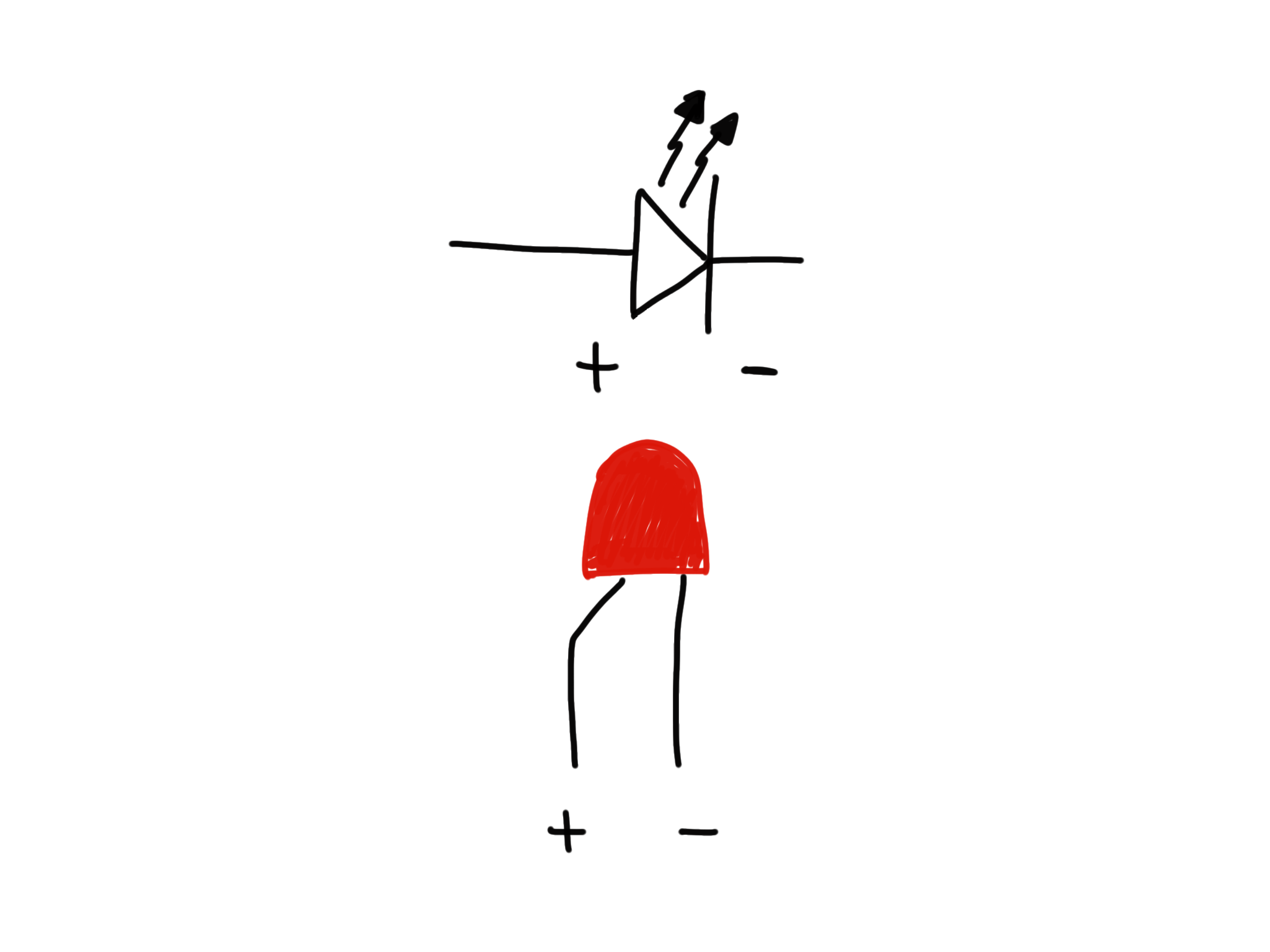
It works exactly like a diode, except it emits light. Here’s how its wires compare to a diode connection:
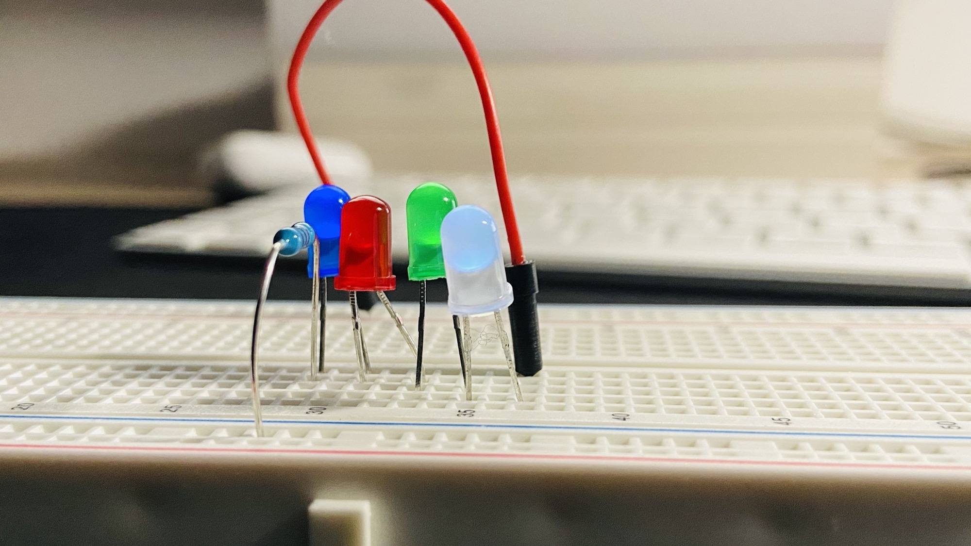
A LED is like a tiny lightbulb, with various color options:
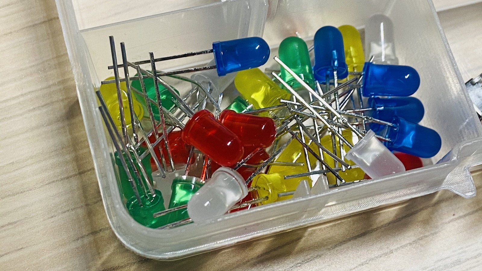
When a certain amount of tension and current applied through the wires, the LED will light up. I’m not going to explain how, just know that it’s a reaction of the material they are composed of when current flows through it.
You already saw how to light a LED with the help of a battery and a resistance.
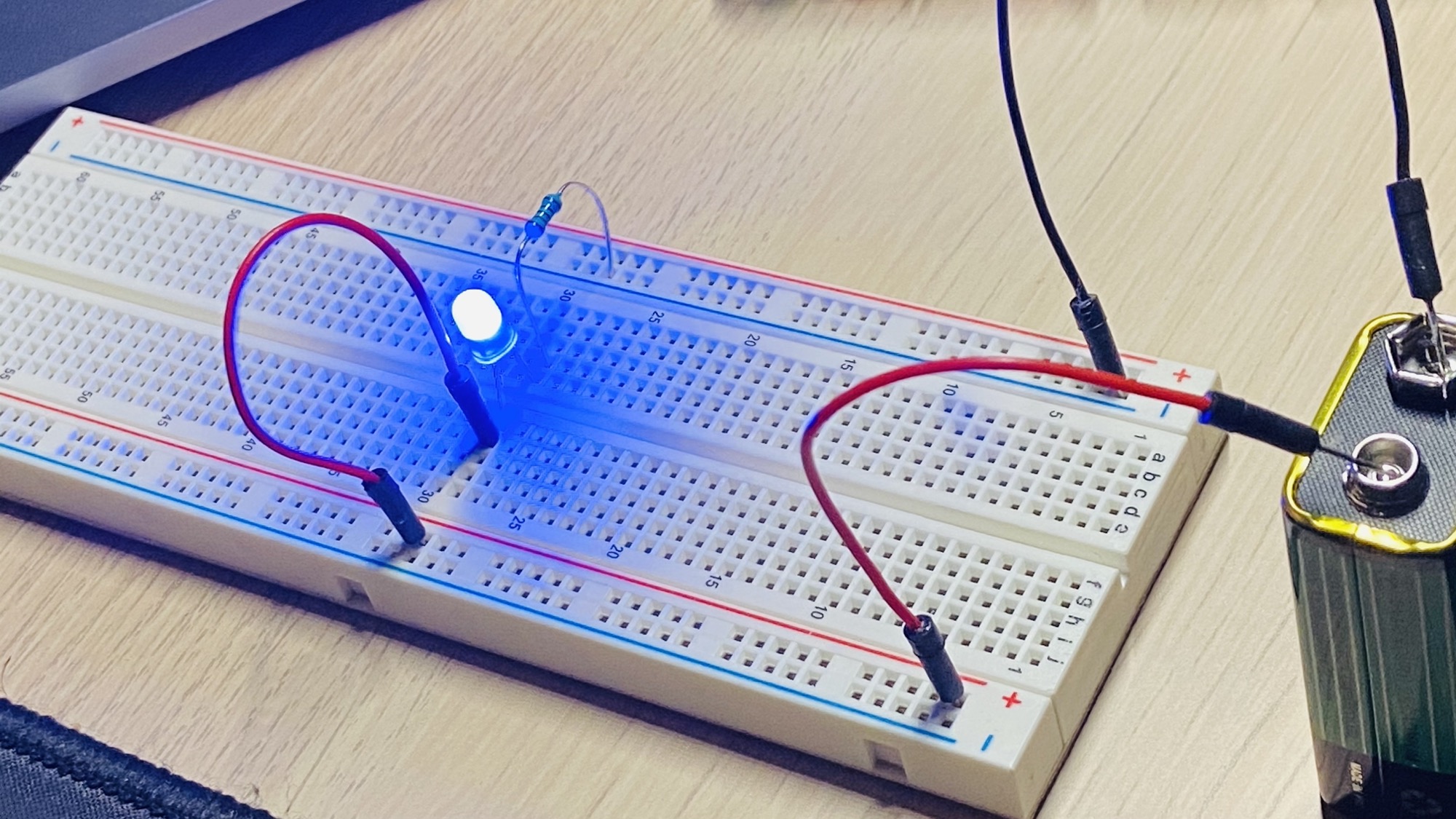
We used a resistance to limit the current flowing through the LED, otherwise it would likely burn because a LED has a tiny amount of resistance, and due to this the current flowing through the circuit would be too much.
WARNING: with too much tension/current the LED can also explode
With a resistance, all works as expected.
Depending on the value of the resistance, the voltage drop on the LED will be different.
Here is an example a 3kΩ resistor. The LED has a voltage drop of 1.87V (the exact value will depend on the LED model). The resistance will limit the current and will have a 7,12V voltage drop:
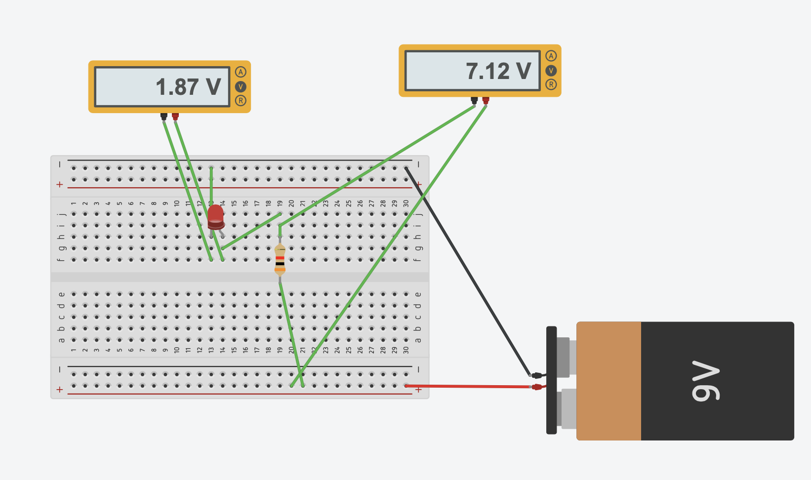
If we had a 300Ω resistor, the voltage drop on the LED would be 2.10V and the current through it will be 22.9mA.
How much current is too much? This is determined by the LED manufacturer, on the specification sheet. The 5mm LEDs I got in the Elegoo box of electronic components points me to this data sheet https://www.superbrightleds.com/moreinfo/through-hole/5mm-red-led-15-degree-viewing-angle-5000-mcd/282/1209/ which states the continuous forward current is 50mA, with a peak of 100mA.
If we put 2 LED in series, connecting the anode of the second to the cathode of the first, we’re going to see they both cause a voltage drop of 1.85V (more or less like before, 1.87V), and the resistance causes a minor voltage drop compared to before, just 5.29V:
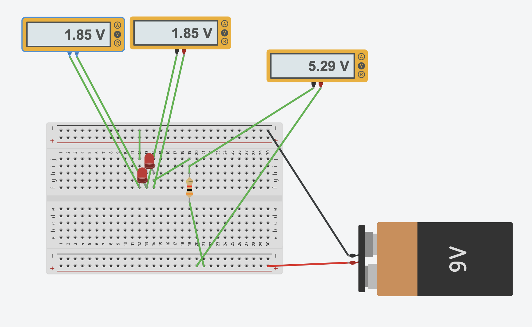
Different LEDs will have different voltage drops, depending also on the color, called nominal forward voltage, and you can get that via direct measurement. It can range from 1.7V up to 4V.
LEDs need a certain amount of current to light up correctly. Typically from 5mA to 30mA.
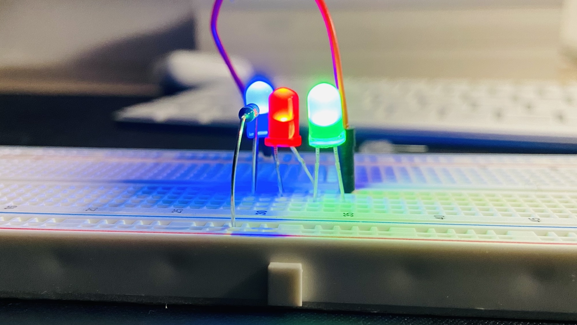
Here are 3 LEDs in series.
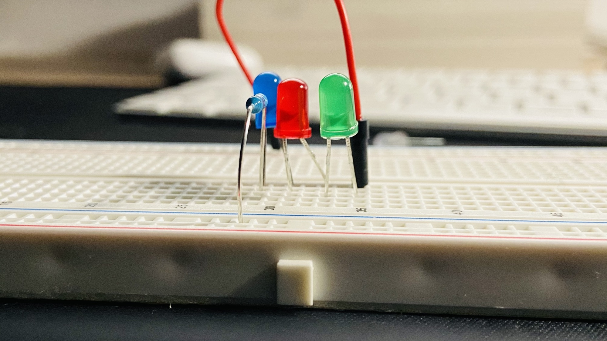
If we apply 9V to the circuit, we’re going to see them shine quite intensely, because the current is 13.3mA:
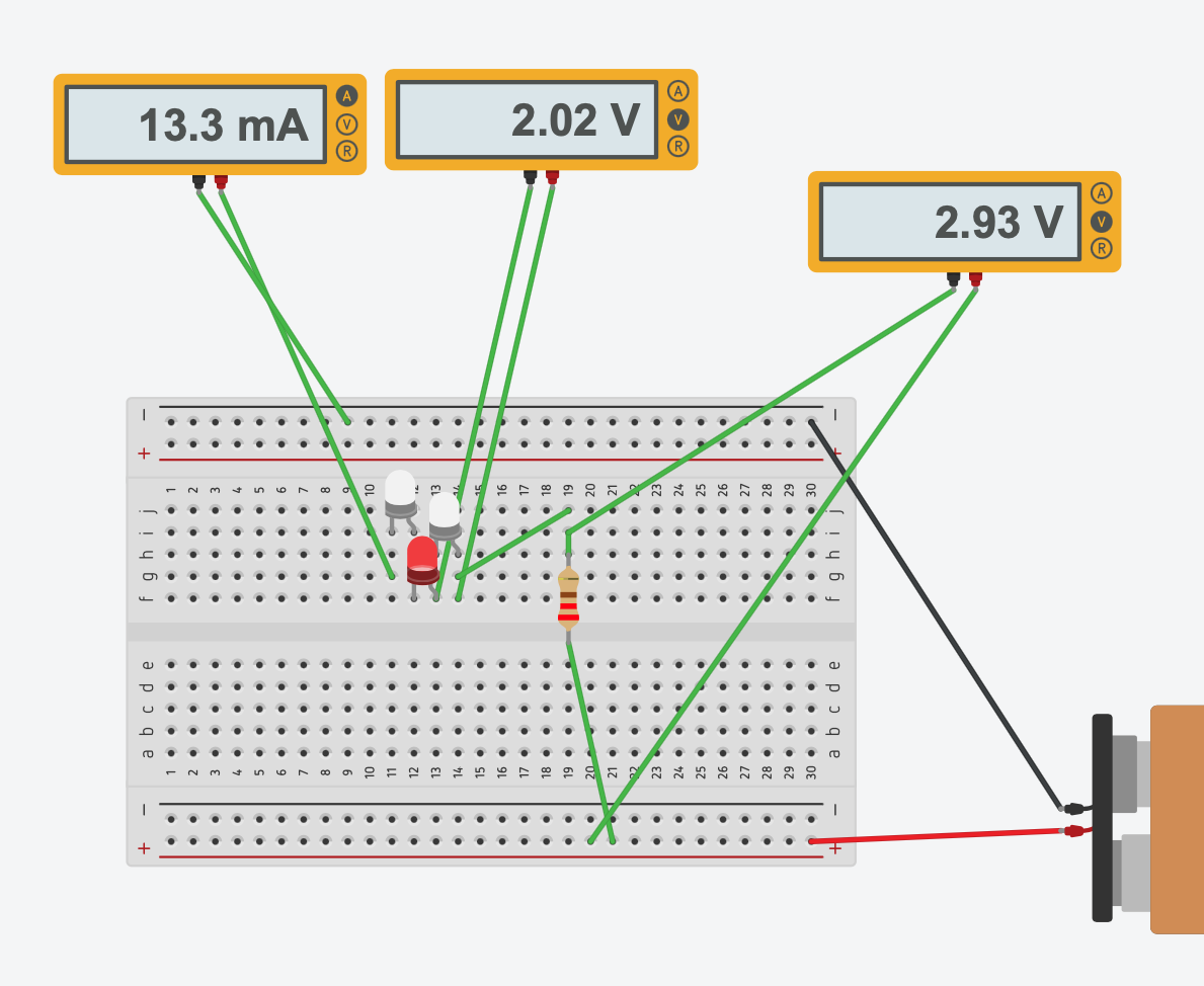
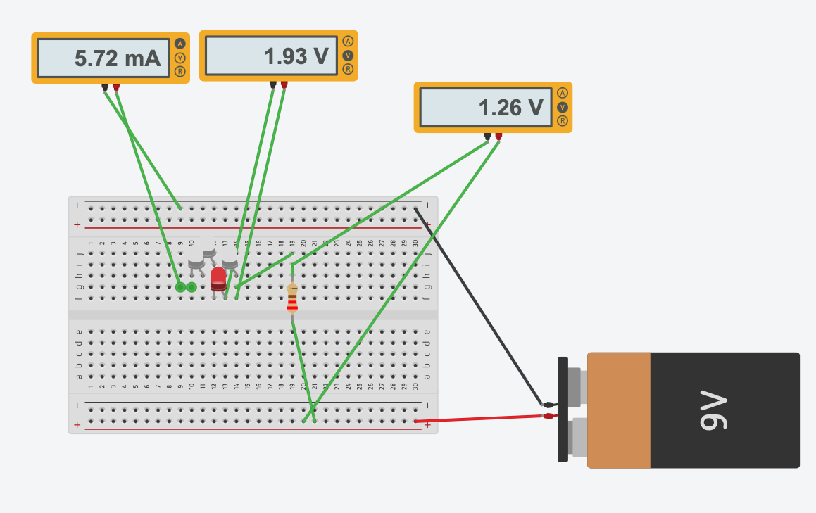
But if we add a fourth LED,
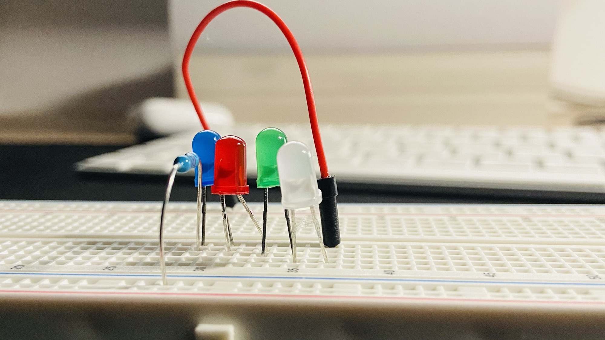
applying the same 9V will cause much less light, because now the current flowing through the circuit is just 5.72mA, not enough to shine a bright light:
Want me to talk about your product? You can sponsor this site.
Related posts about electronics: