Electronic Project: Build a voltage divider
By Flavio Copes
Learn how to build a voltage divider with two resistors in series, why the voltage splits the way it does, and the formula V times R2 over R1 plus R2.
A voltage divider is a circuit that turns a voltage into a smaller one, using 2 resistors in series.
If you put 2 resistors in series (one after another) in a circuit, like this:
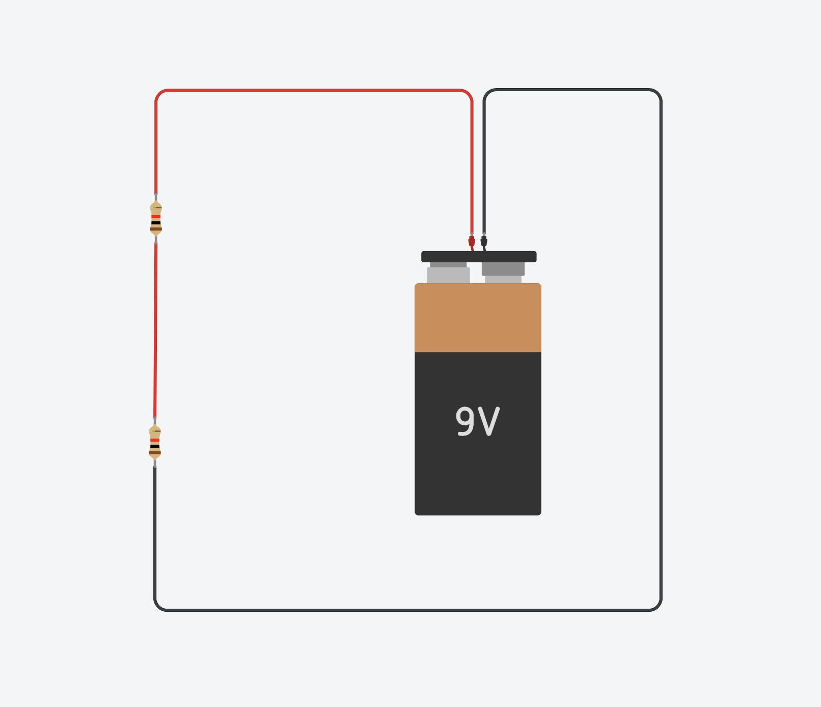
and you measure the voltage drop after the first resistor, you can observe that if the resistors have the same resistance value, for example 1kΩ, the tension after the first resistor is exactly half the original tension.
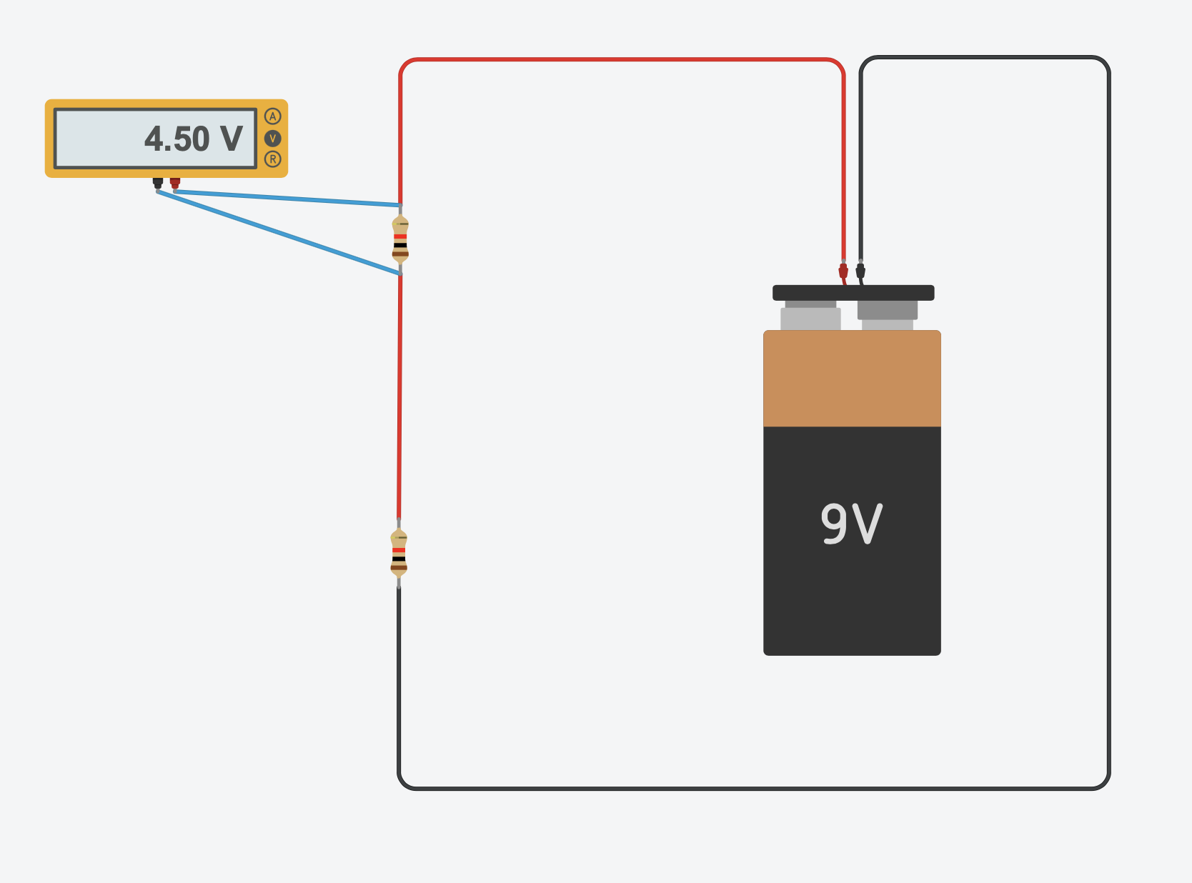
This is because in a circuit the sum of all voltages around any closed loop must equal zero (this is Kirchhoff’s voltage law).
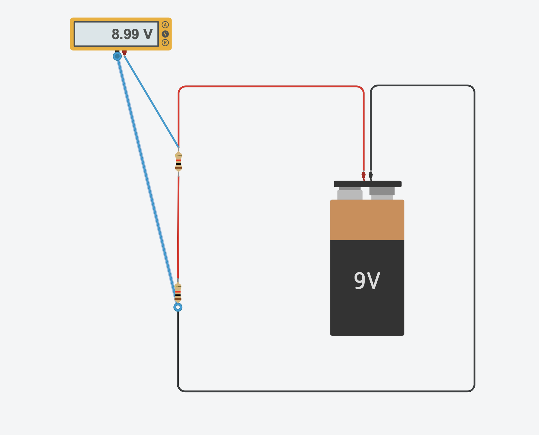
The difference in voltage measured before the first resistor, and after the second resistor, is ~9V, the voltage provided by the battery.
If you double the resistance of the second resistor, the voltage drop after the first resistor is 3V, while the voltage drop after the second is 6V:
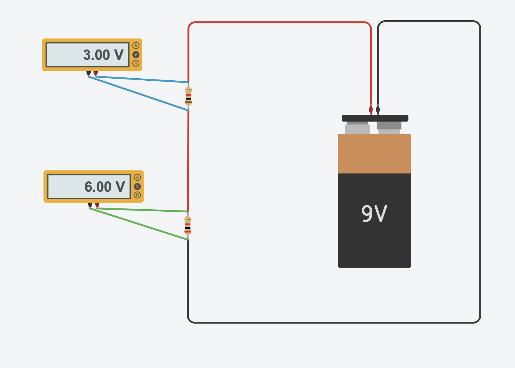
This means that we can adjust the voltage served to a component by using resistors.
The voltage divider formula
The formula to calculate the tension between the two resistors, R1 being the first one linked to the + pole of the battery and R2 the second one, is: V * (R2 / (R1 + R2)).
Let’s check it against the experiment. With a 9V battery, R1 = 1kΩ and R2 = 2kΩ:
9V * (2000 / (1000 + 2000)) = 9V * 0.667 = 6V
That matches the multimeter reading above.
Why does the voltage split like this?
The same current flows through both resistors, because they’re in series. Ohm’s law gives us that current: I = V / (R1 + R2). With 9V and 3kΩ total, that’s 3mA.
The voltage drop across each resistor is I times its resistance. R1 drops 3mA * 1kΩ = 3V. R2 drops 3mA * 2kΩ = 6V.
The bigger the resistance, the bigger its share of the total voltage.
One thing to watch out for
A voltage divider works great for scaling down a signal, for example lowering a voltage into the range a microcontroller pin accepts.
It’s not a power supply, though. Connect a component across R2 and its resistance sits in parallel with R2. That changes the ratio, and the output voltage drops below the formula’s prediction.
It also draws current from the battery constantly, wasting energy as heat. To power a component at a lower voltage, use a voltage regulator instead.
Want me to talk about your product? You can sponsor this site.
Related posts about electronics: