Electronics Basics: Prototyping using breadboards
By Flavio Copes
An introduction to breadboards for electronics prototyping: how the rows of holes connect under the surface, how the power rails work, and when to solder.
A breadboard lets you build and test an electronic circuit without soldering anything. You push component legs and wires into holes, and metal clips under the surface connect them.
Made a mistake? Pull the component out and move it. Nothing is permanent.
In this image you can see a simple circuit with a battery, a resistor and a LED:
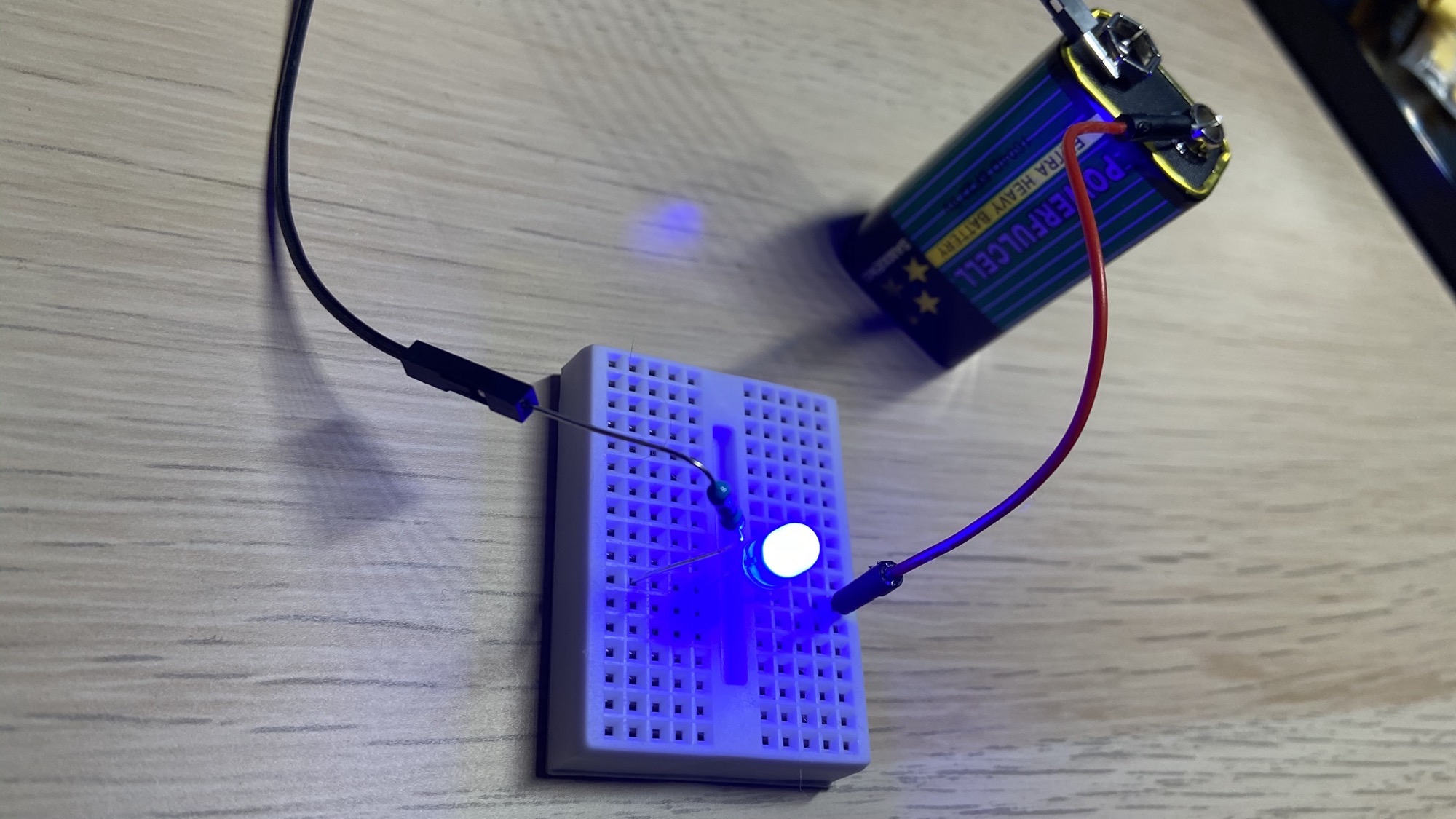
The elements are displayed inside a tiny white box called breadboard:
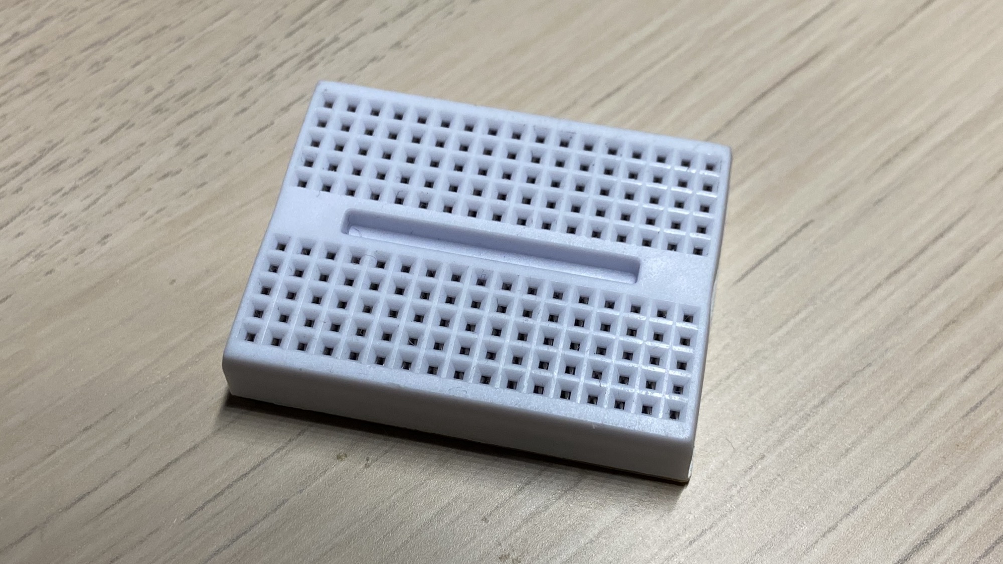
How are the holes connected?
The breadboard has 17 sets of 5 interconnected elements on one side, and 17 sets of interconnected elements on another side.
Under the surface, the 5 holes in a set are connected with each other. To connect two components, plug their legs into the same 5-hole row.
The two sides are separate. That central gap is there on purpose: chips in DIP packages straddle it, so each pin gets its own row.
The holes are 2.54 mm apart (0.1 inches), the standard pin spacing for through-hole components.
This is a tiny board useful for simple prototyping.
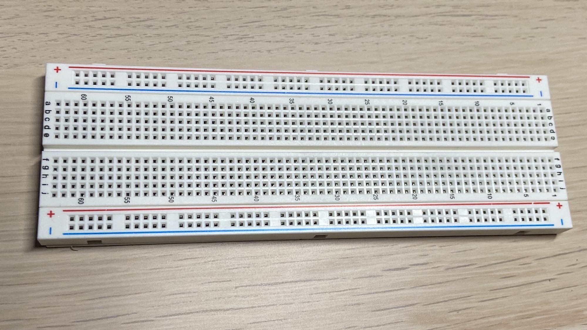
This is a bigger board:
The power rails
The principle is the same, and we have more elements on the outer border, the ones wrapped inside the red and blue lines:
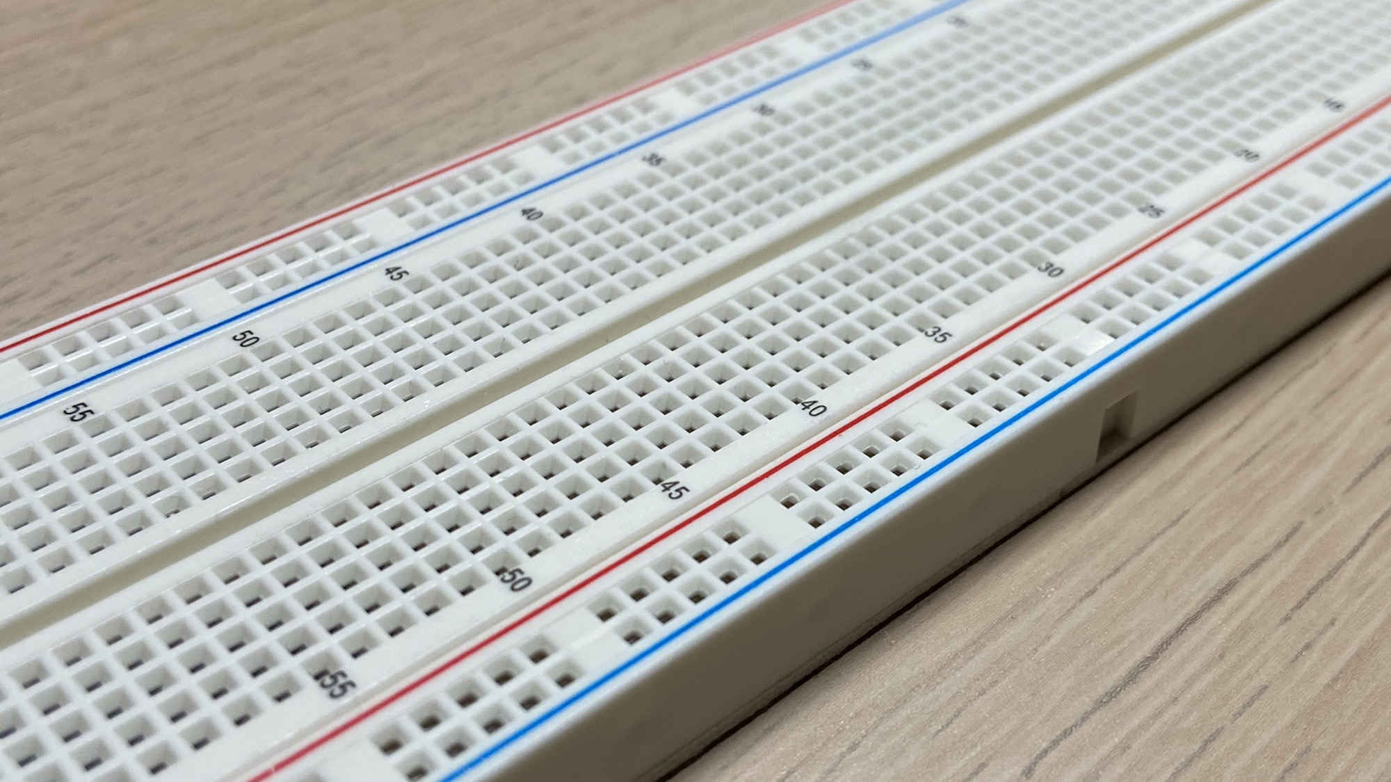
In this case the items are connected longitudinally, orthogonally to the 5-elements sets in the inside of the board:
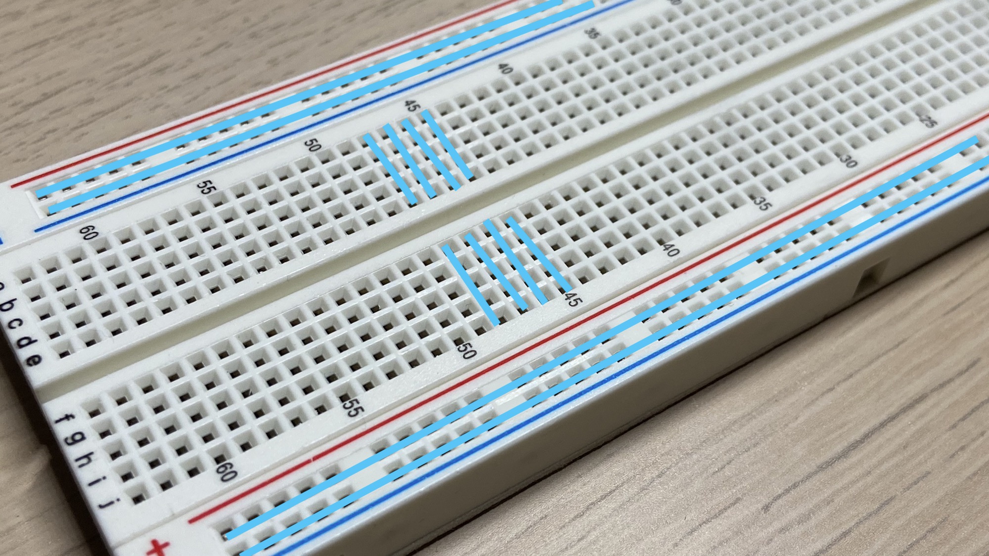
They are used to connect the positive and negative poles of the battery (or any other power source, like a breadboard power supply module that plugs straight into the rails) to the board, so your elements on the board have easy access to them.
It’s common to use red wires for the + positive pole and black wires for the - negative pole:
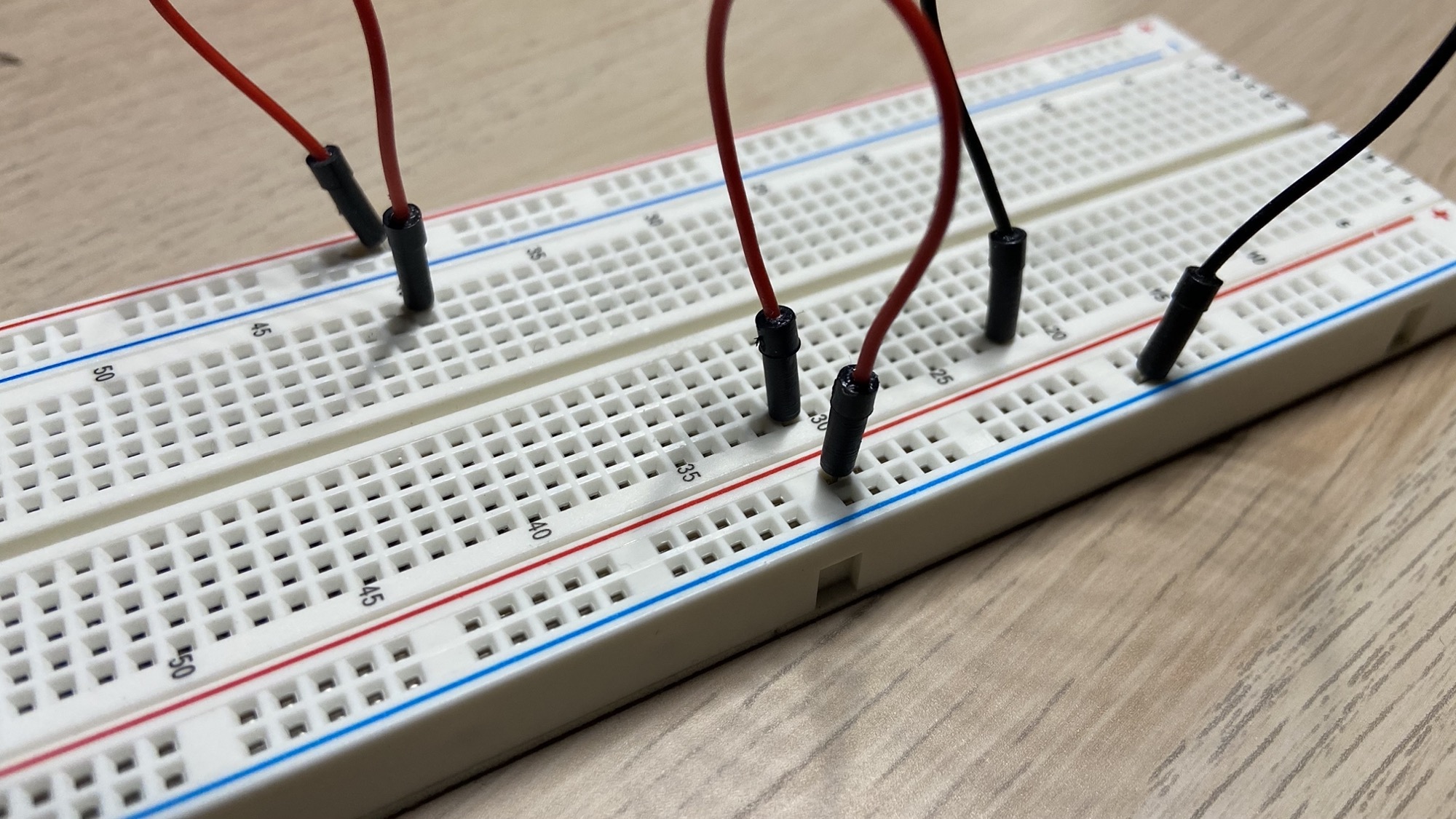
Be careful: on many full-size breadboards each power rail is split in the middle, so the two halves are not connected. The part of your circuit near the battery works, the far end is dead. The fix is a short jumper wire bridging the halves. If the red and blue lines break in the middle, the rail breaks there too.
From breadboard to soldering
You typically prototype a circuit using a breadboard:
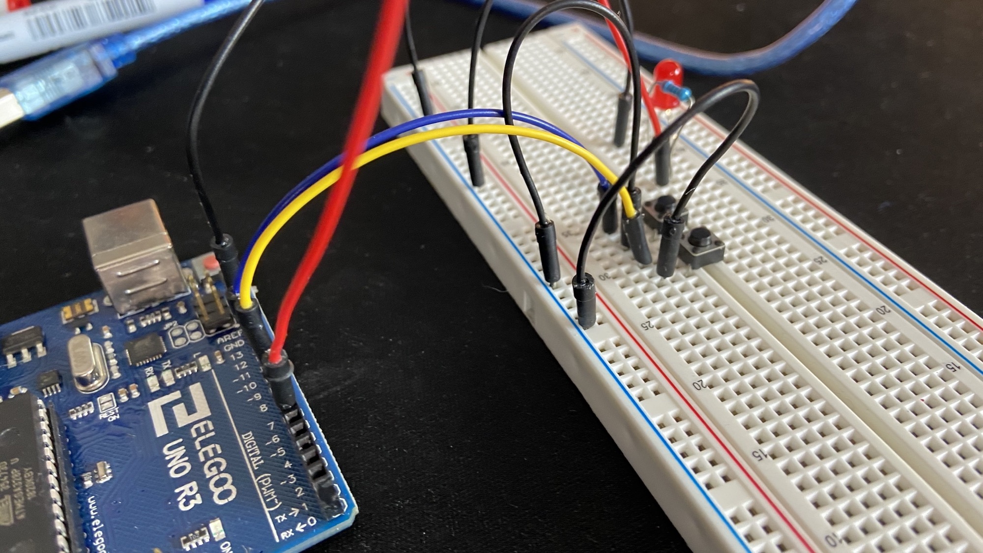
and once you’re ready to move on you can solder it into a perforated board.
Why move on? Breadboard contacts get loose over time, and a wire that half-slipped out of its hole is a classic source of “why did my circuit stop working”. For anything permanent, soldering wins.
Want me to talk about your product? You can sponsor this site.
Related posts about electronics: